Forum Replies Created
-
AuthorPosts
-
The answer we are looking for is “It’s a PTC start device”. Essentially no one uses true relays anymore in this application, so it’s safe to just assume “PTC”.
Those are correct. Good job!
I just replied to your email, Jonathan.
February 15, 2024 at 10:15 am in reply to: Gas dryer: in a video light blue is Line 1 and black wire is neutral #25802Always check the schematic. Some include a very clear chart of which color is what. Some you have to figure out by using your own savvy. They don’t all stick to the usual black/white convention, unfortunately. We’d have to see the diagram to know what the white wire you saw was.
Hi Raja,
First of all, note that the question asks for the two most likely causes.Of the three that you gave, the one that is not correct is “A broken agitator”
Here’s what we said in the lesson:
“If the motor is running, but the machine is not agitating, then you are most likely facing one of two issues, depending on the method your model uses to drive the agitator. On belt-drive models, a worn or broken drive belt causes this issue. Alternatively, on direct-drive models where the motor directly drives the transmission, the most likely cause is a broken drive coupler. This is a small plastic component that connects the drive motor to the transmission.”
The agitator is just that plastic center post with the fins. It is the items that cause it to move (belt or coupler) that usually are the cause of the issue.
Does that make sense?
Tahj – are you getting the Midterm feedback emails I’ve been sending?
Hi Tahj,
It’s easier if you start a new topic for each particular question. Or – if you just want to run a new answer by me, you can use email.See the email I just sent you.
This question is designed to get you to think through the terminology. The fact that it is a “live circuit” means that voltage is applied, but does not necessarily indicate that current is flowing. An “NO” switch being “in its normal state” means that it is open. So, we are measuring across an open switch and would expect to measure the source voltage.
Do you remember what we taught you about current in a series circuit?
It is the same at any point in the circuit. The electrons are all moving or none of them are moving. And if they are moving, they move at the same rate. This is where it is NOT helpful to think of water flow. Better to think of a tightly packed toy train track loop with no gaps between the train cars. If you push one they all move at the same rate.
So you can measure anywhere on the circuit, from wherever you can get the clamp around the wire.
*Power*, which is current AND voltage. The bottom line with loads is power, but since we don’t measure watts, we use amps and/or voltage drop as proxy measurements.
Hi John,
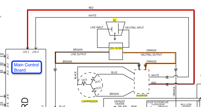
It opens as a pop-up – I wonder if you have a popup blocker?Click here for the image. Does it open?
I’ll embed it here, if that helps

-
This reply was modified 1 year, 4 months ago by
 Susan Brown.
-
This reply was modified 1 year, 4 months ago by
 Susan Brown.
Our answer is basically describing the logical flow of thought – we don’t mean for it to imply that you shouldn’t look at the schematic and determine where/how you’re going to do your measurements.
Hi John,
The answer we’re looking for is, “Follow the line cord inside the machine, measuring voltage as you go, to find where you’re losing the voltage”
Because when there is absolutely nothing going on – no lights or responses to key presses – then you are losing voltage somewhere between the outlet and the controls (the board, assuming it has one).
We don’t give the answer in a neat and tidy way – what we want is for you to apply what we teach about inputs and outputs to this question.
Inputs to a control board would be information that the board can then make “decisions” about. So, sensor data or a feedback signal, for example.
Outputs from a control board are generally things that will be used by the loads or a sub-board, like power supplies.
If you have trouble identifying which of our answer choices fall into which category, send me and email and we can go over that privately (so we don’t give the answers away here).
-
This reply was modified 1 year, 4 months ago by
-
AuthorPosts