Forum Replies Created
-
AuthorPosts
-
I was trying not point out obvious questions on your tests
I appreciate that! But we also have to have something more specific to talk about usually, in order to have a productive “conversation” in these Forums.
Normally for troubleshooting you’ll follow the Ten Step Tango – choose a Load of Interest, etc. But in this case, when the entire appliance is not operating, it just makes sense to trace the power coming in to the machine. You will normally encounter the issue before you get too far into it.
Thanks for the compliment!
If you noticed, we said right above the video that this is the most advanced one in the whole course, so it’s definitely challenging for most of our students.
I’m going to loop one of our more advanced team members in here to help you…
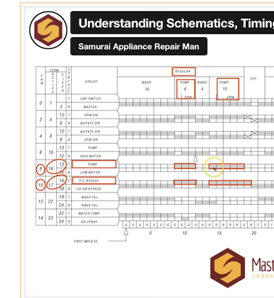
Are you trying to answer Question 20 on the quiz?
The timing chart helps to understand this. See the video at around 10:50 in
This type of schematic reading does take time and practice to get good at – just keep plugging away at it!
If there is a section of the video that you can’t quite follow, let me know a timestamp and we can help you further.
-
This reply was modified 2 years ago by
 Susan Brown.
-
This reply was modified 2 years ago by Susan Brown.
Hi David,
Don’t feel bad – this is a challenging quiz and one that generates a fair number of reset requests.
It’s easier to help if you also mention which question on the quiz you’re dealing with.
For example, Question 3: You arrive on a service call for a washer that’s DOA — no lights, no beeps, no nuttin’. You’ve already verified a valid power supply at the outlet and that the washer is plugged in. Your troubleshooting strategy at this point is to
There is power at the outlet, but not a single thing is working on the washer, including the lights. So, you would Follow the line cord inside the machine, measuring voltage as you go, to find where you’re losing the voltage.
-
This reply was modified 2 years ago by Susan Brown.
Hi John,
You have to think through what you are expecting to be happening in a circuit in order to interpret voltage measurements.
Switches
If a switch is open, you should read a voltage difference across it. If it is closed, you will measure zero volts across it.
So, it depends what you mean by “bad”. And that depends on which action you are expecting from the switch.
There are certain points in the cycle of an appliance you are expecting a switch to open, and others that you are expecting a switch to close. Either of those actions can malfunction.
Loads
Remember that voltage drop across a load is created by current flowing through the load. If you measure 0v across a load, this just tells you that there is no current flowing through it. This means that there is an open somewhere in the circuit. It does not tell you if the load is faulty or not. There is likely a switch, board, or wiring issue in the circuit with the load that is faulty.
If you do measure a voltage difference across a load, say an element, but it is not doing any work (not heating), then that would indicate that you are measuring voltage potential, and the element has failed open.
Does that help?
Okay! I just reset you.
Hi Peter – sorry for the delay in replying!
One of the answer choices for this question is: Trick question! The refrigerant leaves the compressor as a gas. Booyah!
Which, of course, is the correct answer.
Hi Jesse,
It looks like you are talking about unit 5, not 6.
Did you see this topic that we suggested?
Read through that, and then here is some more help.
For #2, you answered
Sub control board power supply
Drain pump power supply
Motor speed feedback signal
Thermistor temperatureTwo of those are correct.
For #3, you answered
Thermistor voltage drop or resistance reading
12 VDC power supply for external loads or boards
Wash motor power supply
5 VDC board power supply for external loads or boardsThree of those are correct.
If you have trouble figuring out which are correct, let me know.
Hi Tyler,
I moved this to be its own topic, by the way.One quick correction. 120v and 240v are “voltage”, not “power.”
Power is both voltage AND current and is measured (usually) in watts.
Let’s look at this one:
A heating element needs to produce 5000 watts of heat. If you have a 120v power supply, how much current will need to be flowing through the element?We are asked to find Current, I
We are given power (watts) P, and Voltage, EIf you look on the Ohm’s Law chart of equations, which one starts with “I = ” and uses P and E?
May 24, 2023 at 12:19 pm in reply to: Math and Ohms Law – A must read if you are struggling with Basic Electricity #25078Good question.
Let’s put it in context, as that is always important when working with these equations.
Let’s say we have a 120v circuit (L1-N) with one load in it – a heating element, for example.
So, we know the voltage drop across that element is 120v. (Don’t worry too much yet about what voltage “drop” is – we’ll cover that more as you continue on through Basic Electricity. All this means is that if you will have line voltage on one side of the element and neutral on the other in a 120v circuit.)
So, the voltage is a set quantity, which means that the product of current times resistance (I x R) must equal 120v.
If the resistance of the element is 100 ohms, then the current will be I = E/R = 120v/100ohms = 1.2 amps.
If the resistance of the element is 200 ohms, then the current will be I = E/R = 120v/200ohms = 0.6 amps.
As the resistance increased, the current decreased, as you would expect since Resistance *resists* or inhibits current flow. So in this context, resistance and current are inversely proportional.
Now let’s say you have a different scenario. You have an element with a resistance of 500 ohms. What would be the current flow if this element were in a 120v circuit compared to a 240v circuit (L1-L2)?
I = E/R = 120v/500 = 0.24 amps
I = E/R = 240v/500 = 0.48 ampsAs voltage increased, current increased. They are directly proportional.
Does that help?
Hi Derrick,
In order to see all of the answer choices again, I would have to set you back to that unit so you could get more attempts on the quizzes. That would erase all the other quizzes after that point and you’d have to retake them. If you want to do that, we can, but we can also just work on the questions you are unsure of here.
For example, here’s one of the questions you missed.
You have a circuit with two lightbulbs in series. If one of the bulbs burns out, what change, if any, would you expect to see on an ammeter (current/amps) reading?
With two bulbs in series, and one burns out, what happens to the current?
(Burned out bulb means that the filament is open.)
Hi Ray – I sent you an email with feedback on that question. Did you not receive it? Check your spam folder if it isn’t in your inbox.
How many loads are in each circuit?
If it is a single load, then Kirchhoff’s Law tells you the answer: the sum of the voltage drops must equal the source voltage. This means if you just have one load in a circuit it will drop the whole 120v.
This is where we encourage folks to use the “Zen trick” when you have parallel circuits, particularly if it is a series-parallel configuration. If you “become the load” and reach out to touch L1 and N, you can figure out if that load is in series with any others or not. (Be on the lookout for shunts!)
We are measuring voltage that switch, from one side with respect to the other. Remember that a voltage reading represents a difference in charge between two points.
With the switch open, we would be measuring L1 on one side, and L2 on the other. Because L1 and L2 are out of phase with each other, this would result in a 240v reading. (See Basic Electricity, units 6 and 9 for a review of 240v service.)
A closed switch is like a wire – essentially zero resistance. When that switch is closed, L1 will continue on through the closed switch until in encounters either another open of some kind, or a load. So, the measurement that Scott gets in the video of (essentially) zero volts means that he is measuring L1 on both of the wires.
One thing that is helpful to keep in mind is that there are two things that will create a voltage difference. One is an open condition, the other is a resistance/load. In the first case you are measuring voltage potential, in the second is voltage drop.
Does that all make sense?
The two things required for current flow is voltage and a complete circuit.
Yes. We have some voltage present, so we obviously don’t have a complete circuit. Something is open somewhere.
Now that I look at it, there is no power coming from L1 with respect to Neutral but there is power coming from L2 with respect to Neutral.
This is Figure 2. These measurements tell us which side has the open fault.
-
This reply was modified 2 years ago by
-
AuthorPosts