Forum Replies Created
-
AuthorPosts
-
August 24, 2022 at 4:00 pm in reply to: Question About Resistance vs Continuity Testing w/DMM #24151
Following up:
A continuity check on a load will show OL if the resistance is above a certain amount. It is good to know the limits of your meter.
Generally speaking, continuity is used on switches/wires to see if that segment of the circuit is open or closed.
Resistance is used on a load to compare to the spec.
There are occasional exceptions, but that’s basically it.
And, of course, it is usually better to use amps or voltage measurements when it comes to AC loads.
If you look at either the schematic or the photos on the last page, you’ll see both 5v and 12v listed. You will also see references to “ground.”
Which type of voltage (AC or DC) uses “ground”?
August 20, 2022 at 1:20 pm in reply to: Question About Resistance vs Continuity Testing w/DMM #24147Hi Peter,
It’s great to see you thinking through these things while in the field. It definitely takes this kind of approach to master troubleshooting – studying, applying in the field, going back to study some more, etc. – and you’ll build your knowledge, skills, and confidence.
I assume that you have gone back over Module 4, unit 7, “Electrical Measurements in Appliance Repair.” We lay all the groundwork there, so that’s a great unit to review. And throughout our courses as well as in the webinar recordings over at Appliantology you can see more testing in action in our videos. That material should help you gain more insight.
I’ll get one of our master techs to take a look at your question as well to answer the more detailed technical question you asked.
Hi Elisha,
First of all, 80% or higher is what is required for Unit Quizzes for Certification, so technically you did pass with an 83%. But, it’s great to shoot for 100% just so you can learn as much as possible. You can request a reset that will give you two new attempts – click the Campus Support tab in the menu, and you’ll see the Quiz & Exam Reset Request form link.
There are two correct answer choices on this question that we are looking for.
I don’t know what you answered on your first attempt, since I can only see the results of your most recent attempt. You answered “No heating.”
That is correct. Because if a dryer has no heat whatsoever, then a likely cause of that would be a tripped thermal fuse or hi-limit, which can happen due to overheating, which can happen due to improper air flow.
However, there is a second symptom that we wanted you to select as well.
Do you recall what your first answer was?(P.S. As you can see, I combined your two posts into one new topic.)
We put this note under the videos in Part 2:
“Note: If you’re following along with the Danfoss app, you might notice some slight discrepancies in the values you get vs. the ones in the video. It looks like Danfoss made some updates to their data to be more accurate. The pressure values they give now are about 0.2 psi lower than they were when we made that video. It’s a small difference and won’t really be consequential in troubleshooting”Does that seem to explain the difference you are seeing?
Look in the App store for “Danfoss Ref Tools”
No current flow – correct. But we do have voltage present. What two things do we need to have current flow? Voltage and a ____ circuit.
PS – I will be out of the office this afternoon, but will check for your reply when I return.
“reading 0 that means there is no voltage drop through the element”
Correct.
Knowing what creates voltage drop, what does this fact tell you about the circuit?
Is there current flowing?
And if not, why not?
Did you read through this one?
What is the significance of the 0 volt reading across the element in Figure 1? What does that tell you?
August 16, 2022 at 9:43 pm in reply to: final exam for the core appliance training course part1 question#34 #24125They need BOTH voltage AND current. Do you remember what we call that? (We emphasize it quite a bit in Basic Electricity)
Hi Frank,
Check out the early portion of the second video in Unit 5. I show that the total circuit current equals the sum of the currents in the parallel circuits (A and B). We also taught previously that a failure in one parallel circuit does not affect any others.
So, if I total = IA + IB, then suddenly IA goes to 0 but IB stays the same, what happens to I total?
I’m glad you’re thinking this through!
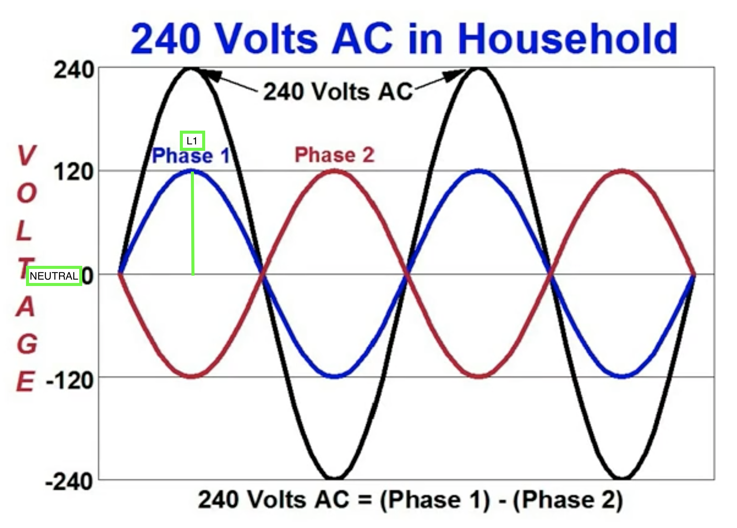
Take a look at this diagram. Say that Phase 1 (the blue wave) is L1. Ignore the other waves. The Neutral line is always at ground potential – the horizontal 0v line, or “x-axis”. The distance between the blue phase 1 line and the x-axis is the voltage difference between L1 and N (120v – the green vertical line).
Does that help?
E is voltage drop across the load. If there is only one load in the circuit, then it will also equal the source voltage.
A typical use of P = I x E for an appliance tech is to take a wattage specification (P) from the service manual/tech sheet and figure out what current you would expect in the circuit, since techs usually don’t have a wattmeter, but can measure amps.
I’m going to run the rest of your answer by the Samurai and will get back to you.
Hi David,
I tried to give some visual analogies in the video in Unit 9 to help with this concept, as it can be a little difficult. If you haven’t already, watch that again to see if it helps.
Electrically speaking, a circuit does not need to have a “neutral”. It just needs to have two poles that are at different electrical potentials to induce current. One has to be more negative in charge than the other.
The way our power supply system is designed in North America, 120vac circuits achieve that by having “Line” and “Neutral”. Line alternates between +120v and -120v. Neutral is always at ground, or “0v”, potential, and thus always has a greater or lesser charge in relation to that line voltage. This difference creates that push/pull on the electrons to generate current.
A 240vac circuit does the exact same thing, but creates a much larger difference between the two poles by having another “line” instead of neutral, and that second Line is out of phase with the first. Whenever L1 is at +120v, L2 is at -120v. Then the next moment, L1 is -120v and L2 is +120v.
As for the complete loop – note that towards the end of the video in Unit 9 I drew circuit loops for both a L-N and L1-L2 circuit.
Does this help? let me know.
-
AuthorPosts