Forum Replies Created
-
AuthorPosts
-
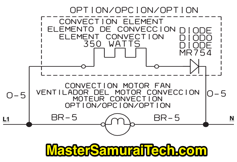
Correct – Current would [answer hidden] in the fan motor circuit. What about the voltage drop across the fan motor?
-
This reply was modified 2 years, 11 months ago by
 Susan Brown.
The questions are: If the diode were to fail open, what would be the effect on: 1. the convection element current (increase/decrease/no change) 2. the convection fan motor voltage drop (increase/decrease/no change) 3. the convection fan motor current (increase/decrease/no change) 4. Total current draw from L1 for all the parallel circuits shown in the schematic
What we have is two parallel circuits. The top one has the element and diode. The bottom one has the fan motor. That’s it.

You wrote: “it does not effect the other circuit”
That is correctWhen one parallel circuit fails open, does it affect the other parallel circuits? (Did you rewatch the first 5 minutes or so of the first video in Mod 4, unit 5?)
Yes! With the Main coil bypassed, the ignitor and booster are *electrically* like the safety – single loads in a circuit, parallel to the others.
So – this is how you answer this question without needing to know the resistance of the loads and doing calculations.
Any further questions about this? I will have to hide some of these answers, FYI, from future students.
It depends – are the loads (ignitor and booster) in series or in parallel with each other?
Correct!
So we are down to the Ignitor and the Booster.
[partially hidden] what is their situation?
-
This reply was modified 2 years, 12 months ago by
 Susan Brown.
Correct –
Now, what about the Safety. What is its situation?
-
This reply was modified 2 years, 12 months ago by
 Susan Brown.
Exactly. That’s all a shunt is: an alternate path that has no resistance.
So, what does this mean for the Main Coil?
Why do they have to go through the main? Is that their only option?
You need to review parallel circuits! You are getting mixed up on the behavior of current and voltage in parallel vs. series circuits.
Please rewatch the first video in Unit 5.
“The detector switch to me looks like it could be some sort of switch or a shunt.” You are onto something here. Do the “Zen trick” on the ignitor and the booster – how do you reach N?
Hi Clifford,
You must have chosen the same answer twice. The software cannot make a mistake in grading.
The order that the answers appear can change each time you take the test, so sometimes that can trip people up. Be sure you are carefully reading the answers before selecting. I just reset that quiz for you.
Did you receive my email about the Basic Electricity Module Exam? Let’s make sure to get that taken care of before you keep moving on.
You are correct that we were reading L2 only in both of those 120v measurements in Figure 1, but it had nothing to do with being in phase. It is because there is an open somewhere along L1 preventing the L1 voltage from being present at the element. Since the element has no current flowing through it, it behaves just like a wire, allowing L2 to be present up to wherever the break is on the L1 side.
That’s correct.
Why were we reading 120v on Meter Reading 3, in Figure 1, before we deliberately disconnected L1, given that there was an open somewhere on L1 all along?
-
This reply was modified 2 years, 3 months ago by
 Susan Brown.
Yes, the issue is an open circuit.
Part 2 is about which side of the circuit has the open – L1 or L2. We can only know that by disconnecting one side and redoing the measurements. (NOTE: in a Line-Neutral circuit, no half-splitting is necessary.) The measurements in Figure 2 are all we need to know which side has the fault.
The question I asked previously was because I’m trying to see if you understand why we measure 120v wrt N (meter readings 2 and 3) in Figure 1, when we know that one of the lines has an open. It’s a good thing to make sure you understand. That’s why I asked if those two measurements are coming from the same line or from L1 *and* L2.
Well, we don’t know if it is a bimetal. There are several possibilities for what could be open, so just know that we have an open somewhere.
I’m not sure what you mean by “unit has a good power source.” All we know is that we have 120v present from somewhere.
Just to make sure you understand: are measurements 2 and 3 in Figure 1 coming from different sides of the power supply (both L1 and L2) or from just one (*either L1 or L2)?
-
This reply was modified 2 years, 11 months ago by
-
AuthorPosts