Forum Replies Created
-
AuthorPosts
-
Yes! Remember, there are only two things necessary to have current flow: voltage and a complete circuit. We have some voltage present, thus we know there is an open somewhere.
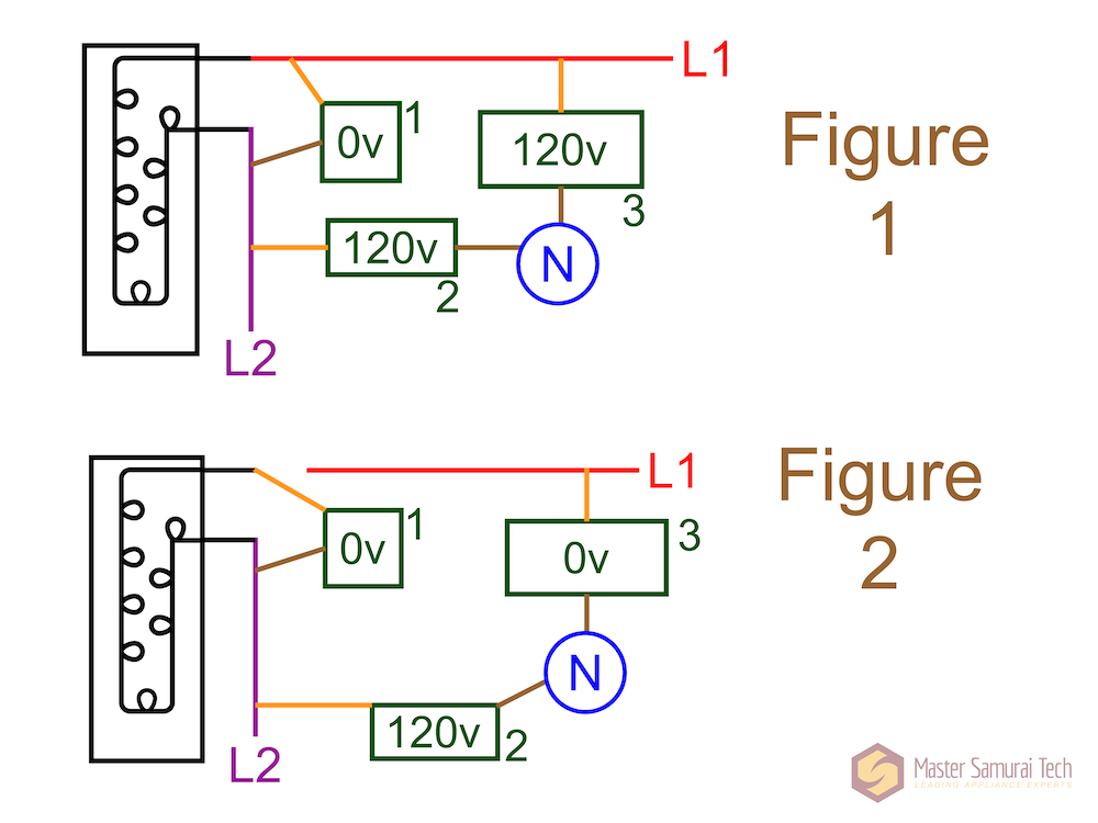
Now we get to a unique thing about L1-L2 circuits. Since both sides of the circuit are supposed to be hot, we can’t tell from the measurements in Figure 1 whether we are measuring L1 or L2 in those “wrt N” measurements.
First of all – do you understand *why* we are getting 120v from either side of the element wrt N, rather than just one side?
-
This reply was modified 2 years, 11 months ago by
 Susan Brown.
“So if I’m reading 0 volts across the heater there is no current flowing through it.”
Correct.
What is the usual type of circuit failure that results in no current flow? (Very generally)
Where do you see a switch? We have not included specific components on this diagram. It is just a very simple schematic showing a 240v circuit with one load, and the 3 voltage measurements that we do. The schematic in Figure 1 shows how the circuit is designed – it does not visibly show any faults that are occurring. It is the voltage measurements that tell us the story of what is going on (or not going on) with this circuit.
Also, re-read what I wrote about measuring voltage across a load (the element, in this scenario). If current is flowing in this circuit, you would expect to measure voltage drop across that element.
You are mixing up a couple of things.
Let’s review:
If you measure voltage across a closed switch, you will get 0v regardless of whether current is flowing or not. It is just like a wire.
If you measure voltage across a known-good load (i.e., it is not open in some way), you will get
– 0 volts if no current is flowing through it, or
– line voltage (120v or 240v) if current is flowing through it.“Measurement 1” in Figure 1 is looking at the voltage across a known-good load. So what does that tell us about this circuit – is current flowing through it?
This one: 44.44*6 just the loose connection?
If you use 36 ohms, you’d be finding the heat generated by the entire circuit.
The primary clue is the 0v reading across the element. When we measure voltage across a known-good load, we are looking for voltage drop.
What does 0v tell us? (Think about what creates voltage drop across a load.)
You cannot make any assumptions about the resistance of the loads.
Did you read the Help Page info carefully?
https://my.mastersamuraitech.com/midterm-exam-help-page/
Let’s start with this – look at the diagram, and tell me which loads have current flowing through them. Pay close attention to the the effect of the closed detector switch on the circuits.
The way we suggest calculating this is in two steps (we show this in the video at the end of Unit 4)
1. Finding the circuit current
2. Then finding the heat generated by *just* the loose connection (using P = I^2 x R, which is “I squared” times R)When you have loads in series, the circuit current is determined by the total resistance in the circuit. (See Unit 4 videos.) Just like you did for question 2 on the Midterm.
But for the second calculation, you’ll only be interested in using the resistance of the loose connection, because that’s the load we are interested in.
The hard work will pay off! We’ve worked with SO many techs over the past 20 plus years – we know that this material makes a difference when it comes to troubleshooting.
No – it is about the equivalent resistance being something less than the smallest resistance in the circuits.
That’s the correct answer. Do you know what the “rule of thumb” is? That is handy to know, and often all you really need to know when analyzing a circuit schematic, rather than calculating the exact number.
Hi Clifford,
That’s correct.Depending on how many digits you keep in your answer to the current calculation, you’ll end up with either 68 or 69 volts for R3. Either is fine.
“The circuit shown below has two loads in parallel: R1 = 10 ohms R2 = 20 ohms. What is the expected equivalent resistance of the two circuits?”
Do you know what equivalent resistance of parallel loads/circuits is?
We cover this in the second video in Basic Electricity, Unit 5.
Hi Clifford,
Remember what I advised you in the videos in Basic Electricity: write down what you are given, and what you are asked to find. This will help you choose the correct Ohm’s law formula.
What information do you have? (hint: be sure to include your answer to Question 3, which is for this same circuit)
This is in Unit 5, FYI, not unit 4.
When the switch is open, current will flow through both the heater element at the bottom of the diagram, and the bulb. When the switch is closed, that creates a shunt which bypasses current from going through the heater, so only the bulb is getting power.
The voltage drop across the entire circuit will always equal the source voltage. When there are two loads in series in the circuit, they will divide up the voltage drop according to each ones resistance. When there is only one load in the circuit, it will drop the entire 120v.
So – what does that tell you about the power output of the bulb in these two scenarios?
-
This reply was modified 3 years ago by Susan Brown.
-
This reply was modified 2 years, 11 months ago by
-
AuthorPosts