Forum Replies Created
-
AuthorPosts
-
You’re welcome! Did you check your spam folder? We are not aware of any issues with our software. Please let me know.
Collin, I don’t know why this is bothering you this way. It is just one true/false question on a quiz that has two attempts. And we are available for clarification if for any reason a student doesn’t follow what we are saying. It is not that unusual for a statement to occasionally strike one person differently from how we mean it. In fact, if we see a pattern of misunderstanding, we will adjust the language to help. You are the only person who has expressed an opinion on this particular item.
The quiz question just says “a general rule of thumb.” That does NOT mean *all the time.*
You said: “Smaller text is either more important than other sizes or it holds the same importance as the rest of the text.”
Attempting to make a hard and fast rule out of this is missing our whole point.
Scott created the video and the slide as well, not just the question.
We do not see the question as contradicting the presentation.
The fact is that some of the very important information on a schematic is in very small print. That is not an opinion.
The largest print on a schematic is often the safety information. While that is important to the lawyers for the manufacturer, that is not very important to a professional appliance technician who already knows the safety procedures, but really needs to know the specs, wire designations, etc. that are usually in small print in order to troubleshoot.
But, obviously, there are some large words that are important to a tech, and some small words that are not.
So, there is not a rule about importance and type size that is true 100% of the time. This is why we put what we did on the slide in the presentation.
But there is a general tendency for the most important troubleshooting info to be in small type. And since most people tend to ignore “the small print” on written materials, we just want to make techs aware that they have to approach tech sheets more attentively.
Again, these are just the realities of technical documentation. Not opinion.
-
This reply was modified 3 years, 3 months ago by
 Susan Brown.
Good questions!
Power (voltage AND current) is what makes a load do work. The output of the load is also referred to as power and is usually measured in watts.
If a load receives more power, it will put out more power.
Have you ever had power fluctuations in your house that caused the lights to dim or brighten?
Yes, a bulb can burn brighter than its rating, but it will shorten its life or, if the surge is high enough, immediately burn out.
Re: Question 12 – When the switch is open and the element is in series with the bulb, the total resistance in the circuit is higher than when the element is shunted.
Higher total resistance means lower current going through the circuit (I = E/R). With less current going through the bulb, it will also have lower voltage drop, and thus lower output of watts (P = I x E).
Does that make sense?
This information is based off of Scott’s vast experience in looking at thousands of tech sheets, not his opinion.
The typed out item on the slide should be combined with Scott’s spoken comments.
In our communication in the course units, if we capitalize a word, make it bigger, put it in boldface or italics, we are 100% of the time trying to indicate importance to you, the student.
On a tech sheet, the size of the typeface does not correlate to importance to an appliance tech in that same way. In other words, LARGER typeface does not equal GREATER importance, and vice versa. Much of the time, it is the reverse. But even that is not a hard and fast rule.
But as a general rule of thumb (in other words, not ALL the time), the more useful info is in the smaller type. We raise this point because it is not the normal way humans interact with text.
Did you read this on the Midterm Help Page?
If current were flowing through all of the loads in the diagram, then the main coil would be in series with the booster AND the ignitor, which are in parallel with each other. So, you’d have a series-parallel circuit scenario, which would make for a more complicated calculation to determine voltage drops (and you’d have to know each load’s resistance).
However, with the circuits configured as drawn, we are saying that you can determine the voltage drop across each load with the information that’s given in the problem statement.
Can you see what’s going on with the circuits that allows this? Pay close attention to the detector switch being closed. IMPORTANT: try the “Zen trick” on the booster or ignitor.
If you do the “Zen trick” on the Ignitor, how do you reach N?
March 12, 2022 at 4:18 pm in reply to: The normal state of the primary and secondary interlock switches #23465When a switch is not actuated, it is said to be in its “normal” state. On the drawing of a switch that we showed you in the video, the “actuating button” is not pushed down – that is the “normal” state.
*Usually*, in the case of a door switch, “actuated” is when the door is closed (and, thus, the appliance will be allowed to operate).
And that is what he says in the video – that the door being open is its “normal”, non-actuated state.
That’s correct. So, you can just try to see if water will come in or not as a test.
When you have a series circuit, is the current different through the different loads, or is the current the same throughout the circuit? (We emphasize this in several places.)
That’s very close. If you keep an additional digit in the current (0.023 amps) you will get 4.6 volts, which will help you zero in on the correct answer choice of the ones we give you.
Yes, through the drain pump winding.
Hi Peter,
One of your answers is correct – “That you are probably seeing ghost voltage and should have set your meter on LoZ or used a loading meter to make this measurement”
Ghost voltage can occur when there is an open neutral, so that is the other correct answer choice.
For Question 36? No, that’s not right.
Can you show me your work? Start with showing me what you get for the circuit current.
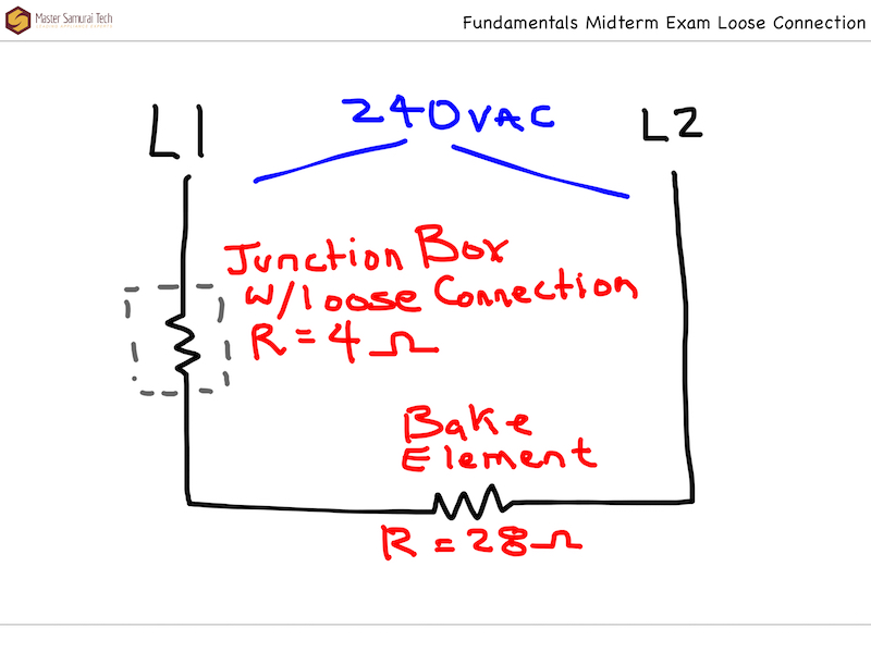
Here’s the question for our reference:
Here is the circuit sketch for an electric oven bake circuit. It has a loose connection that is creating a resistance of 4 ohms. How much heat, in watts, is the loose connection producing?
-
This reply was modified 3 years, 3 months ago by Susan Brown.
You have to think about how current and voltage behave in circuits when you are deciding how to proceed.
For example, we have taught you that current is the same throughout a series circuit. And that current is determined by the voltage supply and the resistance in the circuit. So, if you use I = E/R, then E is the voltage supply and R is the total resistance in the circuit.
What is your new answer to #36?
Let me see you work out Module 4, unit 3 quiz, Question 11. That is similar and is good practice.
“I used p=e^2/r but you are not supposed to use that formula even though I have the supply voltages and resistances.”
When you have more than one resistance in the circuit (in series), and you only want to find the heat generated by ONE of those resistances, then the “E” in that equation has to be the voltage drop across that resistance, not the supply voltage.
We think it is easier to:
1. Find the circuit current (using the supply voltage and TOTAL resistance in the circuit, since that is what determines the current in a series circuit), then
2. Use P = I^2 x R (note that you wrote /R above) to find the heat generated by a particular resistance (where R is that resistance)3600 is not correct for that question. Did you follow the two steps above, or do you see what you did wrong?
-
This reply was modified 3 years, 3 months ago by
-
AuthorPosts