Forum Replies Created
-
AuthorPosts
-
Okay, good.
Figure 1 first:
What does the zero voltage reading across the element (meter reading 1) tell us?
What would you expect to read here if the circuit were working properly?Let’s start with what we told you on the Help Page:
First of all, remember that this is an exam covering “Basic Electricity.” We want you to practice the basic electrical and circuit info that you’ve learned. So, think in terms of current, voltage, voltage drop, open and closed circuits for this scenario.
The problem states that the element tests good (has continuity), yet it isn’t heating, even though there’s some voltage present. We do two sets of measurements to get information on what the failure might be. Knowing that the element is good, we can make a general conclusion about the failure in the circuit based on Figure 1. The measurements in Figure 2 are with L1 deliberately disconnected and give us more info on the failure. Re-watch the video at the end of Unit 6 for a similar, but not identical, scenario. Also think about what the zero voltage drop measurement across a known-good load tells us about current flow in this circuit.
Note: the measurements in Figure 1 do NOT indicate that there is a “bad” (open) heating element. If the element was open, you would measure voltage potential across it.
So – look at the diagram, and tell me what type of circuit we have (series or parallel).
Also, do you understand what we are showing on here in terms of the meter measurements?

That is correct. If you rewatched the video at the end of Unit 3, you saw that we got 211 watts (the resistances were slightly different).
That is current times current, otherwise known as “I squared” and often written as I^2
No (and I just noticed that above you had guessed parallel)
The ignitor and the booster are in parallel to each other.
Let’s see how we know that.
If you started at L1 drawing a line towards N, and you went through the booster, you would not loop around and go back through the ignitor somehow as you keep moving towards N. Same deal if you drew the line through the ignitor.
Electrons are always moving in the most efficient, direct path between line and N.
You have to keep in mind what current is describing – electron movement back and forth between L1 and N (or L1 and L2, if we’re talking about a 240 circuit)
So, now take a look at where the blue lines representing the neutral sides of the ignitor and booster come together and move toward the junction of the Main coil and the branch with the detector switch.
There is a special circumstance that we have described several times in the Module that is happening here. We talked about it especially in unit 5.
If you know what I’m talking about, then you will know which path electrons would take to reach N.
What do you think?
Yes.
(FYI – I’m going to be in and out the rest of the afternoon because of Thanksgiving preparations… I will check in as often as I can.)
Let’s back up.
You are trying to calculate Power, P
You know the circuit current, I (6.67 amps) and the Resistance of the loose connection, 6 ohms.The formula is P = I x I x R
(Current x current x Resistance)I’m not sure where you got 2 x 6. Help me understand!
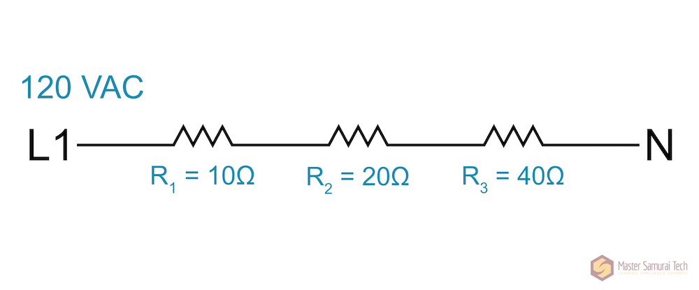
Here’s an example of loads in series. When tracing a path from L1 to N, you have to go through all 3 of these loads.
Back to the Question 8 diagram, if you draw the path from L1 to N, going through the Booster, do you have to also go through the ignitor? (again – ignore the Main coil for the moment.)
Can you show me the numbers you are multiplying together to get that answer?
Correct. So that one is set.
Now, take a look at the Booster and the Ignitor. Ignoring the Main coil for a minute, are the Booster and Ignitor in series or parallel with each other?
It doesn’t look like you are squaring the current.
To square a number means to multiply it by itself. 2 squared is 2×2 = 4. 3 squared is 3×3 = 9.
Try again, making sure you do I x I x R
So does that make it in series with the other loads, or parallel to them?
It is I squared. That means I x I
Also, we only want to find the heat generated by the loose connection. So only use the resistance of the loose connection. Otherwise, you are finding the heat generated by the entire circuit, which is not what we are trying to do here.
That’s not quite it.
Here’s a diagram we are going to work on.
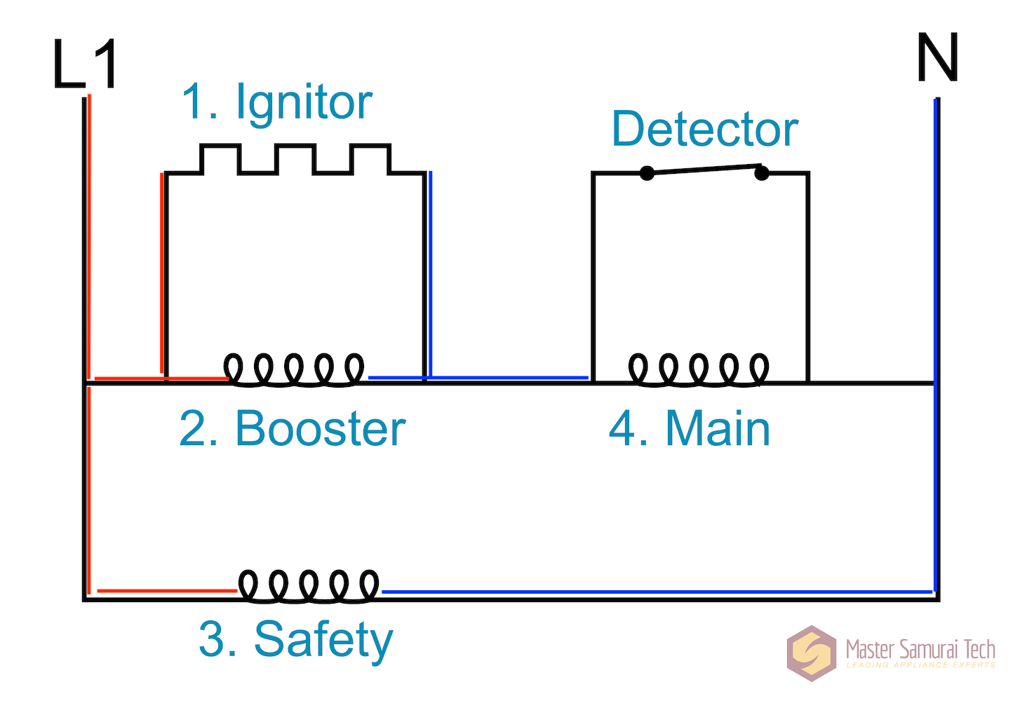
All of the four loads are connected to the same power supply.
When tracing out how each load gets line and neutral, if a particular load can reach L1 and N without going through another load, it is parallel to the other loads. If the tracing goes through another load, it is in series with that load.
Take a look at the Safety. Can the Safety reach L1 and N without going through another load?
Show me the exact calculation please
-
AuthorPosts