Forum Replies Created
-
AuthorPosts
-
Hi Danilo,
Yes, you are correct. The most important piece of information in that question is “open switch.” That means no current. Good job!Done!
That’s it! Do you want a reset?
Are you looking at the Schematic or the Wiring diagram? The schematic is much easier. (As is usually the case.)
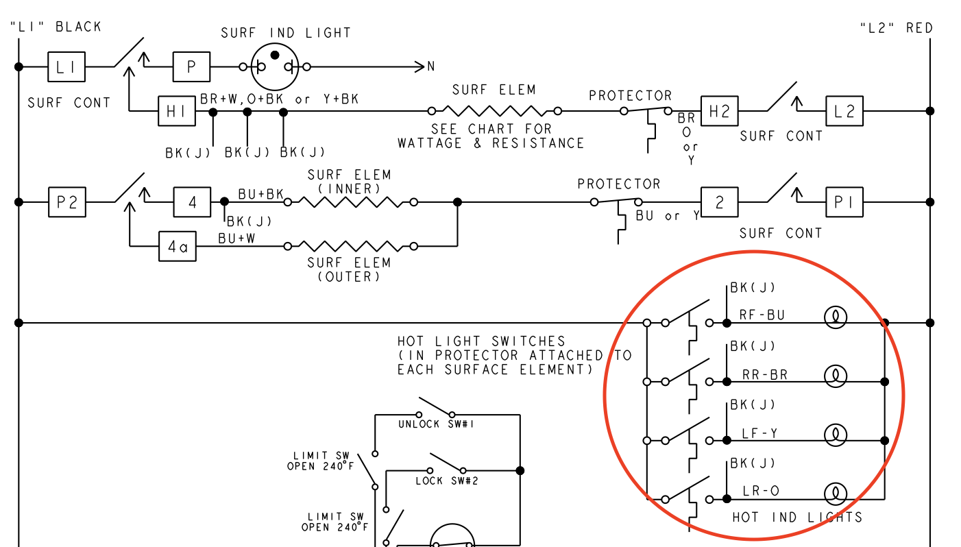
First, let’s make sure you are looking at the correct light. There is a single “surface indicator light” in one location on the schematic, and then there are 4 hot surface indicators lights, one for each burner. You want to find the LF light in that set.
Let me know what you are looking at – how is it labeled?
These are 4 types of coils found in gas dryer valves. All you need to know for the Midterm is that they are “loads” with resistance.
Did you read the Help Page advice on this question?
That is definitely what those readings are showing you. Think about that 0v reading across the known-good element. There is no voltage drop, so we know there is no current in the circuit. We have some voltage, but no current. What does that tell us in terms of the state of the circuit? Is it open or closed?
Those answers are correct! Note – I will hide them so other students won’t see them 🙂
Hi Travis,
For current/amps it is good to keep one decimal place, so 6.6 or 6.7 amps would be appropriate here. That will make your answer just a little bit higher.
Yes, when the switch is closed, this shunts the main coil, as all the current will use that path to get to N. So, if the Main coil receives no current, will it have a voltage drop?
How does that leave the ignitor and the booster? You can tell by doing the “Zen trick” on them. Do they have to go through the Main to get to N?
Hi Brian,
We can help you here.
My first suggestion is that you go through this post, if you haven’t already. Be sure to go through slowly, taking notes and copying the calculations that we show.
Then, for Questions 7 and 8 in the Unit 8 quiz, rewatch the “loose connection” video at the end of Unit 3. The scenario is similar – two resistances in series. See if you can follow what we do on the video and recreate it on paper. Let me know if there are any steps you don’t follow.
Those are both correct!
Excellent!
That is exactly how learning is supposed to happen. You go over material, get as much as you can figured out, the periodically revisit it when you realize you don’t have it mastered yet, which helps it to click in even stronger. It is not a completely linear process.
You’ve described good study habits – thank you!
Hi Starobin,
L2 is supposed to be hot (120v), but it isn’t in that scenario. There’s an open somewhere on the L2 side preventing current from flowing in the circuit.
Hi Ben,
1. Yes to both, basically. You’ll create the folders in Goodreader, which will also store them that way. It’s straightforward – just start using the app and you’ll see.
2. We don’t have files available as a massive download, nor do we recommend people try to do that. You’ll just end up with thousands of files you will never use. As you know, we recommend you have an SOP (Standard operating procedure) with your jobs that involves downloading the docs you need ahead of time. Occasionally, the file you need will not be in our downloads section and you’ll need to request it. You’ll gradually build up a library of docs for models that are common in your area, and will be adding to it regularly.
The number of times you’ll go on a job without advance notice is small, and then there’s no guarantee that the doc you would need would be in the big stash. So, it’s not worth changing your SOP for this circumstance. And, hey – sometimes the tech sheet is still on the appliance!
-
AuthorPosts