Forum Replies Created
-
AuthorPosts
-
Hi Davon,
Here are two quotes from the unit on Natural Gas:
1. When the gas reaches a customer’s meter, it passes through another regulator to reduce its pressure to under 7″ wc, if this is necessary.
2. Most household appliances that burn natural gas operate on 3 to 5″ WC pressure and have their own pressure regulator.
These are not talking about the same regulator. Quote 1 is referring to a regulator in the meter.
And here’s the quiz question:
Question #34 – Gas appliances that use natural gas have their own regulator which regulates the gas pressure to
So the quiz question is asking about the info in quote number 2.
Hi Davon,
Unfortunately this Forum software doesn’t make it easy to attach an image. Please email it to me (susan at mastersamuraitech.com) OR tell me the approximate time stamp in which particular video.
You’ll have access to your courses until your enrollment ends. It will only end in December if you don’t continue with the monthly subscription.
You can either update your payment method (at the bottom of your My Courses page) and just let the system bill you monthly, or if you would rather pay in blocks, then just get in touch with me in December and I can send you an invoice for how every many months you want to pay for.
As you’ve seen, we occasionally use a test as a learning tool itself, and not just testing exactly what we’ve already taught explicitly. This type of experience stretches a student and helps things to click more firmly after the struggle to figure it out.
As you go along, you’ll expand your schematic diagram “vocabulary” – in other words, recognizing what symbols and phrases mean.
Sometimes you just have to pore over the schematic, reading notes. For example…
Underneath the schematic they say, “Note – Bk(J) denotes black jumper wire on each radiant element between terminals 4 and S.”
So, that tells you what BK(J) is, and then you might notice that they indicate wire colors. For example, the LF burner that we focused on in this exercise has a Yellow wire to the left of the light. Up near H1 where the 3 jumpers come up, the 3rd notation says “Y+BK” which indicates where the LF light is tied in.
That H1 circuit is just shown once, but there would be 3 of those for the three single elements.
Then, the RF Blue wire comes in at the other Jumper, that is part of a dual-element burner. (You’ll see that over on the wiring diagram, too.)
Does that all make sense?
This is a diagram that takes some noodling over. We get asked about it a lot. But, it’s a great teaching tool!
Once you’ve completed the courses, you can continue getting exposure to schematics by watching our webinar recordings over at Appliantology!
🙂
Hi Davon,
They need an AC power source, not DC. Review the material in the Variable Frequency Drives unit if that doesn’t make sense.That’s from whatever is beyond left field! I’d have to learn that stuff all over again. It’s been 35 years, give or take. Plus, there are places like Khan Academy that have lots of math instruction online.
I ran this by the Samurai. He said that you sometimes have to wiggle the probes around to get good contact with the metal inside the slots of the receptacle. You should read near 120vac if you have one probe in the hot slot and one probe in the neutral slot (the longer slot).
If you still are getting strangely low numbers, maybe someone could film you doing the measurements, showing the meter and its settings, and you could email that to me and we’ll take a look.
Hi Jacob – yes, that’s correct!
Those are correct! Has this information helped you?
Where are you putting the two probes – one in either slot of the outlet?
And are you sure you have the meter set on measuring VAC?
Let’s try this exercise.
Here are two loads in series in an L1-N circuit, with resistances of 100 ohms and 50 ohms.
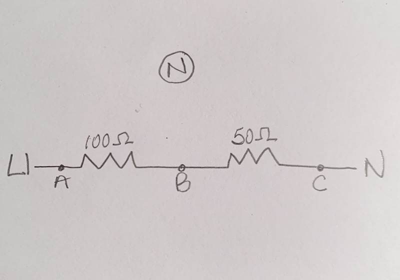
I’ve labelled 3 testing points: A, B, and C. There is also a separate Neutral point that we can use as a reference.
If you did the following voltage measurements, what do you think you would get?
1. A with respect to C (in other words, one probe on A, the other on C)
2. A wrt B
3. B wrt C
4. A wrt N
5. B wrt N
6. C wrt NIf you don’t know all of them, that’s fine – just answer what you think and we’ll go from there.
Good questions.
First of all, don’t think of voltage as “getting” to loads. Think more of voltage being “present.” Current is movement.
The same current will be measured at every point in the load.
The voltage you measure will depend on what your reference point is. It’s always “with respect to” (“wrt”) something.
If you put your probes on either side of a load, you’ll measure the voltage drop across that load (Ed = I x R).
I’m going to create a diagram that shows this better later today and will post it, to help you out.
A series circuit is just describing a circuit with one or more loads in it, where they are connected one after another.
The relationship between voltage (E), current (I), and resistance (R) in a series circuit is E = I x R. This tells you how changing one value will affect the others.
In the real world, in a typical circuit, the source voltage will be set – either 120 or 240.
Then the circuit current will be determined by the total resistance in the circuit.
I = E/R
So, if R is increased, I will decrease. That is true regardless of what the source voltage is.
(In Unit 8, you’ll learn that you can calculate the “voltage drop” across each load using E = I x R, which is another way to use that same equation.)
1. Your example is correct IF the two loads have the same resistance. If they don’t, then the voltage drops will be different (proportional to the resistance… E = I x R).
Go back and look at the Midterm Exam in Core, Questions 2, 3, and 4 where you had to calculate a scenario with 3 loads in series with different resistances.
2. Current is electrons hopping from one atom to the next. They are like tightly packed billiard balls in a track – they are either all moving at the same rate, or not at all. So, in a circuit, the electrons are moving at the same rate throughout the wire, regardless of where they are (on the line side or the neutral side).
The difference between the two sides of the circuit is the voltage. The neutral end is always at ground potential. The line (or, “hot”) end is rapidly shifting from +120vac and -120vac, creating the charge that causes electrons to move back and forth towards the more positive side of the circuit.
This motion of the electrons through a load creates a voltage difference (“drop”) from one side of the load to the other. The sum of the voltage drops across the loads that are in series will total the source voltage.
Does this help?
-
AuthorPosts