Forum Replies Created
-
AuthorPosts
-
Let’s take these one at a time.
In question #5 my new answer will be: R(eq)= 1 divided by 10= .1, 1 divided by 20 = 0.05, 0.1+0.05 = 0.15 ohms. I = E/R = 10 + 15 + 20 = 45, 120/45 = 2.7 amps
When you start working on a question, pay close attention to what information you are given and what we are asking for. In this case, you have two loads that are in parallel, and are asked to calculate the “equivalent resistance” of those two loads. In other words, from the point of view of the power supply, what is the resistance? You started with the formula for R(eq) (which has a mistake, but I’ll get to that in a minute), but then did a calculation of current.
1. The R(eq) calculation. The correct formula (that we give you in Unit 5) is 1/(1/R1 + 1/R2 +…). So, you found the bottom part of that whole fraction (0.15) but didn’t do the final “1 over”. In other words, 1/0.15.
2. If you were asked to calculate the current in this circuit, you would just do I = E/R(eq)
That’s correct. Now, what about the ignitor?
What do these two answers tell you about the function of the detector switch – how does it being closed effect the main coil?
Hi Jordan,
Let’s start with Question 8.
Take a look at the diagram, and do the “Zen trick” on the booster coil. What path do you take to reach N?
Hi Michael,
You assume correctly. Without voltage, there will be no current flow.What two items are absolutely necessary for current flow to happen? (hint: you’ll need to be able to answer this on the final exam, so it’s good to make sure you know it now!)
Hi Dylan,
See this video where we step through a similar calculation in more detail, and see if that helps. If not, you’ll need to show me your steps.
Hi Miguel,
Good question! I’ll give you a short answer here, because you’ll learn even more about AC power in the units ahead.
With DC, it’s easy to picture a battery with a positive and a negative pole or terminal, and how the electrons will flow in one direction if they have a complete circuit from one pole to the other. The terminals never change their charge.
In an AC circuit, the polarity of the power supply terminals switches constantly from positive to negative, causing the back and forth movement of the electrons.
Keep going through the next few units, and let us know if you need more details.
Hi Richard,
Good question, and glad to see you are paying attention!
Part of the challenge in teaching Basic Electricity is that it is a pretty complex topic, and we’re only skimming the surface to equip appliance techs with enough knowledge to assist their troubleshooting, without diving so deep that it’s overwhelming.
When it comes to power transmission, remember that P = I x E. So, in that case, you can see that if you are given a fixed number for Power, increased voltage will result in decreased current.
But we also have the relationship of E = I x R, which shows voltage and current being directly proportional. In an appliance setting, if you are looking at an entire circuit, the value of E is usually fixed (either 120v or 240v). Thus, the variables tend to be I and R. However, as you will learn more about in Unit 8, we can also calculate the voltage drop across a particular load. The higher the current, the higher the voltage drop.
So, you not only have to understand the mathematical relationships between these electrical properties that Ohm’s Law is helping us to see, but the context that we’re using them in.
It takes some time and effort – but please keep working at it and asking us questions!
Just to add to what Sam said…
Using a steamer to make sure you’ve removed all of the ice is one way to help make sure you won’t get a repeat of the problem.
Also, besides what Sam described, some models of fridges actually have a little cal rod heater that is used to prevent the freezing of the condensate drain.
I suspect that your resetting the timer or not was more of a coincidence, and didn’t really contribute to the fix.
December 30, 2020 at 10:30 am in reply to: Module 3 unit 4 video (Parallel vs Series Parallel Circuit #21223That’s correct!
December 29, 2020 at 8:41 am in reply to: Module 3 unit 4 video (Parallel vs Series Parallel Circuit #21218Hi Richard,
No apologies necessary! This is what we are here for.Good question. There is a difference between the two diagrams. In Fig. 6-9 in the Kleinert book, there is a “series portion” and a “parallel portion”. The two loads in the series portion are in series with that whole parallel portion.
Here’s the diagram you’re talking about in the video:
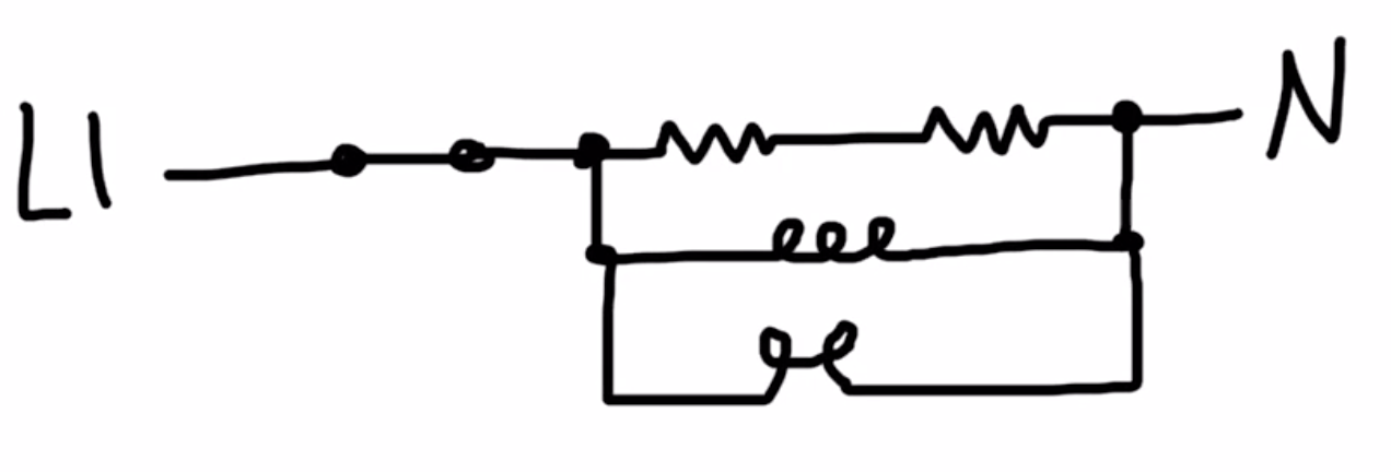
The two loads that are in series, in the top circuit, are parallel to the other branches, not in series with them. Imagine electrons flowing back and forth from Line to N. In the Kleinert circuits, all of the electrons will have to travel through that series portion no matter which parallel circuit they also go through. In our set of circuits, that is not the case. Do you see the difference? If not, let me know, and we can continue to discuss. However – you’ll learn more about series and parallel circuits in the next unit as well, so that may be all you need.
Okay – let us know if you do need further help on anything!
I just emailed you
You don’t have to earn Certification, but I don’t understand why you won’t let us help you understand this information more. I’ll email you about this later today.
No worries!
That’s correct! Good job.
-
AuthorPosts