Forum Replies Created
-
AuthorPosts
-
Hi Daniel,
Doing conversions can be a little confusing until you get some practice with them. Sometimes it helps to practice with something you are more familiar with first.
For example, think about meter, kilometer, and millimeter. These are items you can picture, and relate to.
A meter is about the same as 3 feet (a yard).
A kilometer is about the same as a half of a mile.
A millimeter is a tiny little length.Kilo is 1000 of something
Milli is 1/1000 of something.So, a kilometer is 1000 meters. (You could phrase this as “converting” 1 kilometer to meters, which gives you 1000 meters. 5 kilometers would be 5000 meters.)
A meter is 1000 millimeters.
Or, you could say the opposite. 1 millimeter is 1/1000 of a meter.
For example, if someone wanted you to convert 1 meter into kilometers, would you take 1 meter and multiply by 1000, or divide by 1000?
Answer that, and we’ll go from there.
“Usually” is an important word! Here’s what we say in the unit
How long this valve is kept energized depends on the model, but it is usually kept on for 90 to 120 seconds.
So the best choice out of the possible answers we gave you is
Probably, but it depends on the model
Hi Josh, welcome!
Any of the units that you have completed can be gone back over, including looking at the quiz results. That is an important way to study for your exams!Let me know if you have any other questions.
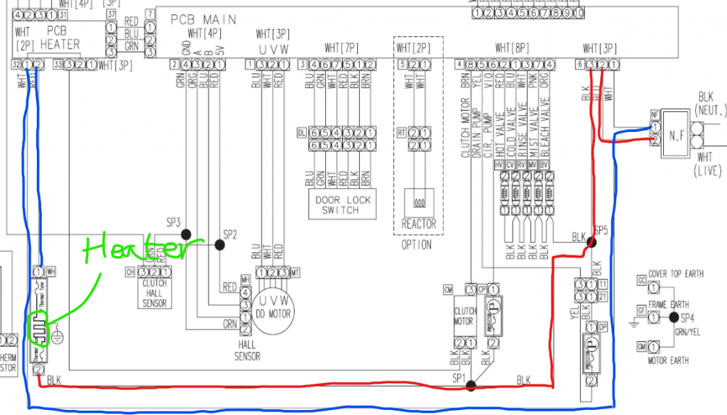
Hi Maksym,
Sorry about that – it shows up on my end. Sometimes it helps to close your browser and start fresh, and maybe clear your cache. Please let me know if it shows up for you after trying that.
I’ll include the image below.
Hi Joe,
Great job!
Most appliance repair companies are familiar with Master Samurai Tech and would be impressed with the fact that you earned Certification.
We have a Forum at Appliantology for techs who are looking for a job.
Also, we have a partnership with the Mr. Appliance Franchise organization to provide training to their techs. While I don’t have knowledge of each individual franchise location, as a whole Mr. Appliance is a great company. I know there is a location in the Indianapolis area.
I should be getting my next batch of Certificates from the printer shortly after New Years. I can always communicate via email to a potential employer if you don’t yet have the Certificate in hand.
Merry Christmas to you!
You can go ahead and put your answer here. I’ll just hide it after commenting on it 🙂
Hi Cynthia,
We’ll grade your Midterm this morning and email you about the results. You can move on a little in the course, since you do have another attempt at the Midterm if needed, but we advise people not to make too much progress until they’ve passed the Midterm.The quiz on Mod. 4, unit 2 is a one-question humorous one, so don’t worry! 🙂
The Final exam is largely based on the unit quiz questions that you encountered throughout the course. The biggest difference is when you get to the Open Answer exam and have to write definitions and do a few calculations on your own. The final exam has a higher first-attempt passing rate than the Midterm, FYI.
So the best way to study is to review each unit and quiz, to refresh your memory. If you’ve been keeping a notebook, that will help a lot.
Keep a calculator, pen, and paper handy.
Hello! That never used to show up. I think that when we rolled out our new website, somehow that quiz setting got changed. We are going to be going through and removing it. So – you can just ignore it!
Hi Darren,
Those are the same courses, we just added the word “Advanced” to help folks understand that they are supposed to be taken after completing the “Core” course. Also, it allowed us to Bundle them together and refer to them as the “Advanced” courses.
But, I now realize that when you go to the “My Courses” listing, they don’t have the word “Advanced” in front of them.
Let me get your opinion – take a look at your “My Courses” page.
If we add the word “Advanced” in front of the Refrigerator, Washer & Dryer, and Oven & Range courses, would that make the course titles too long or harder to find what you’re looking for at a glance? Or would it be better to do so that others don’t have the same question you did?
Thanks!
December 3, 2020 at 8:40 pm in reply to: Video on “importance of understanding of reference “ ? #21019At around 1:02-1:03 he is talking about the reference you use to take a voltage measurement, which is what I was talking about above.
Voltage is always a difference between two points. You put one probe on the point of interest in the circuit, and the other probe on a reference point.
You can watch the second video in Module 3, unit 8, for a quick review of making voltage measurements.
The webinar he talked about is at Appliantology. Have you activated your student membership there? You’ll need to be logged into it to view this:
https://appliantology.org/topic/72236-samsung-dryer-troubleshooting-and-electric-circuits-review/
December 3, 2020 at 5:46 pm in reply to: Video on “importance of understanding of reference “ ? #21016Please tell me which video this is in – which unit in the Troubleshooting module. And an example time stamp where he says that. Thanks!
December 3, 2020 at 5:32 pm in reply to: Video on “importance of understanding of reference “ ? #21014Hi!
I’m assuming you are talking about the importance of understanding what your reference point is when doing a voltage measurement. Voltage is always a comparison between two points. That’s why you use two probes. You are measuring at one point “with respect to” another. A common reference point is a known-good neutral. A common voltage measurement would be looking for 120vac at a component with respect to neutral.
Does that make sense? (And, is that what your question was referring to?)
Yep!
Maybe this will help:
-
AuthorPosts