Forum Replies Created
-
AuthorPosts
-
Hi Darren,
Glad you enjoyed the Refrigerator course!
The Oven and Range Final Exam will cover material from Module 4 (microwave ovens) and the technical presentations from the Case Studies. It will not cover material from Modules 2 and 3, since we have module exams for those.
There isn’t a strict course order that we recommend, but so far you are doing what most people usually do – Core, Refrigerator, Oven & Range, Washer & Dryer, Adv. Troubleshooting.
Enjoy!
You’re on the right track. In order to have current flow, you need to have different voltages on either side of the load. For example, Line and N, or L1 and L2. Having L1 on both sides of the load means no current flow. So – any voltage drop?
Hi Andrew,
If you have L1 on each side of the motor, will current be flowing through it? Remember, you have to have current going through a load to have voltage drop.
I reset you.
I encourage you to ask for clarification whenever you need it. We wrote questions in such a way as to encourage people to think about the concepts that we are teaching and pay attention to details (very important for anyone who is a “technician”). But every student has unique needs – different language skills, different educational background, etc. So, that’s one reason we have these Forums, so that you can ask for help if something doesn’t “click” with you.
Please watch the first video from 8:50 to 9:00.
“Load” is a term you will see used a lot in the course.
A lightbulb is an example of a load. Question 12 did not ask for an example of a load.
When we talk about loads in appliances (the things that are performing their job – heating, moving, lighting, etc.), we will say they are “doing work” when they perform those tasks. “Power” is the measure of that work. A heating element does “work” when it heats up. Then we can ask “how much power is the element putting out while it is doing work?” and would find that answer in units of watts.
Hello!
The answer is “load.”A load is a component in a circuit that, when current flows through it, will do work (and – as you’ll learn, create a voltage drop across it).
It showed up!
Hi Daniel,
What the Samurai shows you in the videos is the result of decades of collecting tools, so you definitely don’t need to start with a big purchase.
You can get started with a selection of basic hand tools and a good meter, then add on as needed.
Your Appliantology membership is now active, so you can use the “Dojo” Tech Forum to get input from other working techs. Lots of guys there love talking about tools!
The easiest way to think about this is to remember that the equivalent resistance of parallel loads will be smaller than the smallest resistance.
The compressor windings, which are also in parallel, have resistances of 4.4 ohms and 6.25 ohms. The condenser motor is over 1000. So, the equivalent resistance of the motor and the compressor will not be much affected by the condenser fan resistance.
Do you know what the equivalent resistance of the compressor windings is?
Jaime – did you get my email?
Hi William,
They are showing up for me, so I’d like you to try something and let me know if it helps.
Close your browser and clear the cache. Then, reopen it and try again.
Let me know if that helps. If not, please let me know what you are using to access the course – computer or device, and what browser.
Hi Chuck,
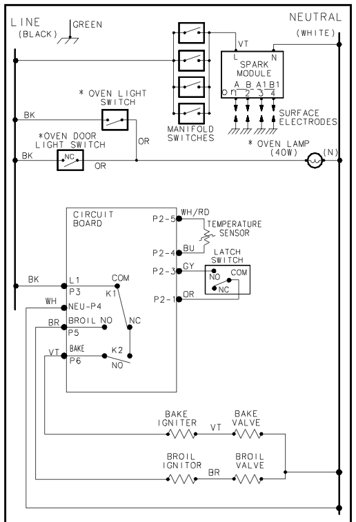
Hmm – I can see them on my end, so I’m not sure what’s going on there. Whenever you encounter something like that, it’s a good idea to refresh your computer – close the browser, clear you cache, then start fresh.Please try that and let me know if the image shows up for you.
I’ll post a copy of it here just in case
Hi Jaime – I’ll email you, since we are discussing specific answers…
Hi Everardo,
How about you go through the Basic Electricity module again.
Now that you know the questions on the Midterm exam, you would be able to look for the information that would help you to answer them.
Before I reset you, perhaps you want to write down or copy the Midterm questions.
Let me know if you want me to reset you.
Sure – I reset you.
-
AuthorPosts