Forum Replies Created
-
AuthorPosts
-
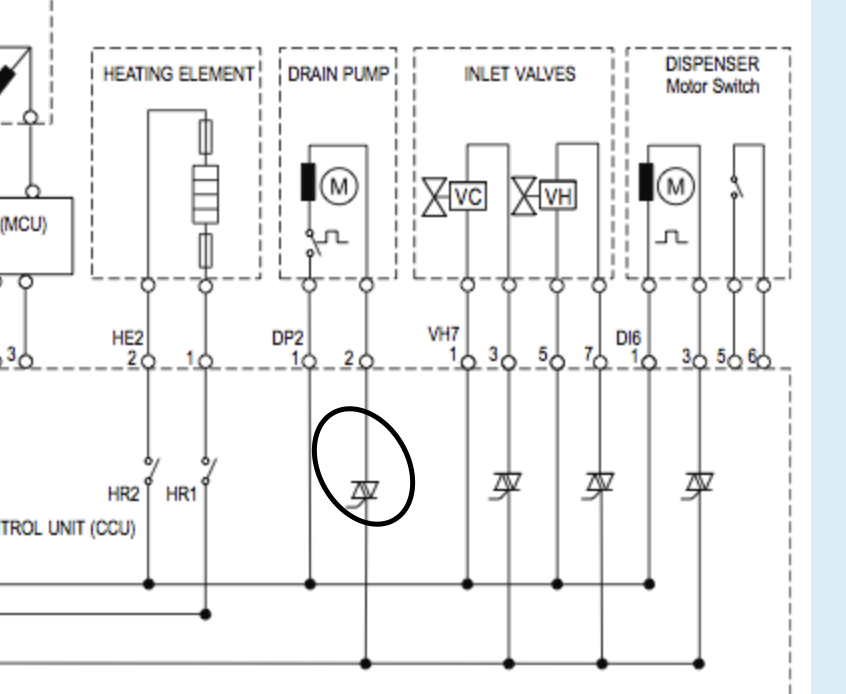
You are correct – that reference sheet doesn’t have a triac symbol. That’s why we show it in a later unit when we discuss them. Maybe you can draw it on your printout!
5 and 21 are correct.
Question #3 – You arrive on a service call for a washer that’s DOA — no lights, no beeps, no nuttin’. You’ve already verified a valid power supply at the outlet and that the washer is plugged in. Your troubleshooting strategy at this point is to
The answer is just kind of the logical way to proceed. Your outlet is fine, but the whole unit is “dead”. You would just follow the line (power) cord up into the machine, measuring voltage until you find where you’re losing it.
Question 10
From the Electronics module, unit 3
 April 1, 2020 at 11:45 am in reply to: clarification on the core appliance repair training course midterm review #18838
5. L1, L2, and neutral in 240 vac appliances
a. How to use voltage measurements to locate the fault in an electric dryer that is
not heating- disconnect one of the lead to the element and then test each wire to ensure that each line voltage is supplying power to the elementBasically, yes. We’re wanting you to be familiar with basic concepts of voltage, voltage drop, and current in a series circuit, as well as L1-L2 circuits. The video at the end of Unit 6 is good to review.
April 1, 2020 at 11:42 am in reply to: clarification on the core appliance repair training course midterm review #188374. d.ii. the total circuit current-no difference
this is incorrect. The videos at the end of Unit 4 are good to review for this.
April 1, 2020 at 11:41 am in reply to: clarification on the core appliance repair training course midterm review #188364. Parallel circuits: i thought you treated each branch as a separate circuit but used that philosophy on the last exam and i got it wrong
a. The voltage present at each branch is it the same or does it vary? I believe it varies
b. Does the current vary or is it the same in each branch? It’s the same throughout the circuitWhich question do you think this philosophy led you wrong on? #5? You got that one incorrect because you talked about voltage in your answer, and we were asking for equivalent resistance.
Your answers for a and b are not correct. Review unit 5.
April 1, 2020 at 11:37 am in reply to: clarification on the core appliance repair training course midterm review #18834#2 the difference between the two is that the voltage pushes the electrons and voltage drop is the effect of the voltage pushing its self through a load
Better to think of voltage as simply the difference in charge between two points. This difference in charge will cause electrons to move if they have a complete circuit. For example, if you measure voltage across an open switch. It is potential voltage, because there is no current flowing (since the switch is open).
Voltage drop is the difference in voltage caused by current (electrons) going through a load. Your meter probes will be on either side of the load.
Voltage doesn’t push itself – it pushes electrons.
#3b so if i need to find current id need to do I=E/R
yes, where R is the total resistance for the whole circuit
#3c so to calculate voltage drop you would need to do E=I*R
yes, where R is the resistance of the load that you are focussing on
#3d so no matter what the current stays the same and resistance affects the amps and voltage mostly
amps is the same thing as current. Total resistance of the circuit affects the circuit current. But when you are looking at voltage drops across individual loads, that is determined by the resistance of each load.
#3f to calculate watts id need to do P=I^2/R
that should be * (times) R, not divided by R.
Otherwise, yes – but first you need to calculate the circuit current, I.March 31, 2020 at 10:51 am in reply to: clarification on the core appliance repair training course midterm review #18830Series circuits
d. Is current the same or does it vary in the circuit?- i believe that it would differ because of voltage dropPlease rewatch the 1st video in Unit 5. We clearly state that current is the same throughout a series circuit. Very important to understand.
f. How to calculate the heat (in watts) generated across a particular load.- take the source voltage and the ohms of the load and divide them
No, E/R = I (current).
Rewatch the “loose connection” video at the end of Unit 3. See if you can recreate the calculations we show you on your own.March 31, 2020 at 10:46 am in reply to: clarification on the core appliance repair training course midterm review #188283. Series circuit
b. How to calculate the current in the circuit- can you help me out on this one i understand but not enough to fully explainIf you know the total resistance in a circuit, and the source voltage, you can calculate I using a simple Ohm’s Law equation. Can you see which one?
c. How to calculate voltage drop across each load- you take the source voltage and divide that with the ohms from each load
Voltage divided by ohms is how you calculate current, not voltage drop. (I = E/R).
From Unit 8:
When we talk about Voltage Drop, we’re always talking about a specific load that has current flowing thorough it. That’s why it makes no sense to talk about the Voltage Drop at a wall outlet that we’re checking with our meter, for example, because there’s no current flow and no load (the meter doesn’t count as a load– a good meter should never load the circuit enough to make a difference).
In the course of doing its work, a load will have a Voltage Drop across it that is proportional to the resistance of that load. Remember E = I * R. You have to keep straight here what this is referring to. For example, if you’re looking at the voltage drop across a load, you would look at
E(Voltage Drop across the load) = I(current flow through the load) * R(resistance of the load).
March 31, 2020 at 10:41 am in reply to: clarification on the core appliance repair training course midterm review #18827It will take me a little time to go through these, so I won’t be able to reply to everything all at once.
2. The difference between voltage (potential difference) and voltage drop.- can you help me out with this question i don’t understand how to answer this one
From Unit 8:
Voltage is most simply described as the force that pushes electrons along in a circuit (the actual movement of those electrons being what we call current). Voltage is the prime mover or cause in a circuit. Everything else that happens in the circuit is an effect. When there is a difference in voltage between two points in a complete circuit, then electrons will move: they will be pushed away by the more negative voltage and be sucked in by the more positive voltage, a push-pull kind of a deal. The directed movement of electrons from that difference in voltage between two points is called current.Voltage Drop, on the other hand, is an effect caused by electrons being forced through the resistance of a load by that voltage difference between two points.
This concept about Voltage Drop is key, so we’ll state it one more time: A Voltage Drop across a load is produced when current flows through that load.
Many of those controls are not nearly as precise as we’d like them to be! They rely on customer interaction to optimize the settings.
Hi Carlos,
Please read this blog post as well as the comment by Son of Samurai underneath it which specifically mentions motors.
https://appliantology.org/blogs/entry/1059-why-amps-are-the-definitive-measurement-in-ac-circuits/
Does that answer your question?
First of all, of the three choices we give you, one of them is completely incorrect (the sealed system) and the other one less likely, given the scenario (evap fan).
When the freezer is set to its coldest setting, it will keep most of the cold air in the freezer. Depending on the model, this could make it difficult for enough cold air to be distributed to the fresh food compartment, no matter what setting you have there.
In a single evaporator refrigerator, there may be two settings, but with the freezer set to “coldest”, the refrigerator setting may not be able to override that enough to maintain below 40 temps.
It’s at least the first thing you’d want to try, before more intensive troubleshooting.
Make sense?
We figured out why Chrome didn’t like the way we had that audio clip set up and fixed it – will play now on Chrome!
March 24, 2020 at 9:56 am in reply to: Module 8 Unit 2 Variable Frequency Drive System Audio Problem #18807We figured out why Chrome didn’t like the way we had that audio clip set up and fixed it – will play now on Chrome!
Hi Rodney,
Which quiz are you talking about?
-
AuthorPosts