Forum Replies Created
-
AuthorPosts
-
1) is there a tool or method for testing the windings on these compressors? They are 2 inches from the left wall of the machine compartment, very difficult to see the windings let alone test them with leads.
You run into that every now and then, and it is tricky. Clip-on leads are probably the best way to deal with it, but those configurations are always a bit of a pain.
2) all was good with the refrigeration course, and what I’ve learned, right up until last week when I got a call for an LG refer, and the compressor only had 2 windings.
I assume you mean that it had one winding with two terminals. Your typical split phase compressor has two windings (but three terminals), and that doesn’t sound like what you’re talking about.
If you mean one winding with two terminals, that would be a linear compressor. I’m fairly certain that we cover them in the course. But in any case, we have an in-depth webinar recording that covers the technology:
Can I assume that because neutral comes into 32-1 that 32-2 is also neutral?
Yes, that’s exactly what we wanted you to see! This schematic doesn’t do a very good job of indicating which wires are line and which are neutral (a problem you’ll run into plenty in the field), but you spotted the giveaway.
That 32 connector is just a relay on the heater PCB (you can see that by looking at the picture of the board on a separate page). All it does is open or close the connection between 32-1 and 32-2, meaning that the red wire going to the heater has to be the neutral side — which, of course, means that the black wire is the line side.
That rectangle that L1 and L2 (less confusingly called line and neutral) are connecting to is not a conductor. Rather, it’s indicating a control board. A very simple one, but a control board nonetheless. All those lines connecting to the rectangle are showing various connectors. You can see a similar sort of thing going on with the PTC. The rectangle there is not indicating a conductor — just a discreet component.
The control board can use internal, electronically controlled switches to supply line or neutral through those various wires. And if it’s working correctly, it will never create a short between line and neutral.
Hi, Ronny — it looks like you haven’t submitted an MST Student membership request form at Appliantology yet, which would explain some of the trouble you’re having. You should be able to find the form in the third unit of the Appliantology 101 short course.
Once your membership has been set up, you’ll be able to request a manual in the Appliance Service Manual Requests forum.
Both AC and DC solenoids exist. They’re made slightly differently depending on what kind of power they’re supposed to receive, but they work in the same way: the current flowing through the solenoid coil creates a magnetic field, which in turn moves a plunger.
AC solenoids can be powered by AC or DC and operate just fine. DC solenoids, however, must be powered only by DC. If you powered one with AC, you would burn it out.
Great! Glad to hear it.
June 24, 2020 at 10:52 pm in reply to: Basic electricity module 5 schematics unit 4 troubleshooting part 1 last video #19301Not at all — in this example, we’re just showing the board closing the internal connection between J1 pin 1 and J2 pin 8. The other pins on those connectors all have different functions. Some are for supplying neutral, some for line, and some (like the terminals for the thermistors) supply low voltage DC power. J1 pin 7, as an example, supplies line to the compressor whenever the board chooses to run it.
That’s the power of control boards — they may act as switches sometimes, but they’re very smart switches that can switch line and neutral to lots of different loads intelligently.
June 24, 2020 at 2:31 am in reply to: Basic electricity module 5 schematics unit 4 troubleshooting part 1 last video #19289Think about what’s present at each of those points your leads are on. At J1 pin 6, you have line voltage — 120 VAC.
And then at J2 pin 8, you have neutral. That may not be as easy to see, but that’s why the Samurai drew in that blue closed switch on the control board. The board is acting simply as a closed switch, making J1 pin 1 and J2 pin 8 electrically equivalent points.
So when you put one lead on line and the other lead on neutral, what will your meter measure?
In a split-phase compressor, the start and run winding are arranged in a “V” shape. The point of the V is where the Common terminal is, and the two lines that extend from that point are the windings. The Start and Run terminals aren’t directly connected to each other, since they’re each at the end of one of the lines of the V.
This is why you always measure the most resistance when you put a lead on the Start terminal and one on the Run terminal. When you do that, you’re reading the resistance of both the start and the run windings.
Does that make sense?
You’re heading in the right direction!
When a circuit uses 120 VAC, that means it’s using just one leg of the household power supply — either L1 or L2 (doesn’t matter which).
The reason why we call split-phase motors “split phase” is because of the two windings they have — run and start. Due to the way these windings are configured relative to each other, the magnetic fields produced by the current flowing through them is out of phase. They’re not 180 degrees out of phase like L1 and L2. Depending on the motor, they can be as little as 30 degrees out of phase. But that little difference in phase is enough to get the motor going from a dead stop.
So split-phase motors take single phase power, but the start winding creates a second phase for as long as it’s in the circuit.
Let me know if anything still isn’t clear.
The purpose of a grounding wire is to keep the neutral side of the power supply at ground potential — i.e., 0 volts. Ground should not be high resistance. The entire point of it is to be a 0 resistance path to ground. If a grounding wire becomes high resistance, that is actually a fault condition.
Because the grounding wire keeps neutral at ground potential, you can safely touch a neutral wire without any risk of electrocution, even if there’s hundreds of amps of current flowing through it. If the path to ground were to become high resistance, however, then there could become a voltage difference between neutral and ground, which would cause you to get shocked when you touch neutral.
I think this video will help to explain these concepts further.
I have had a number of instances(especially in microwaves running on an AFCI) where there is repeated tripping of the AFCI breaker.Have had licensed electricians out who have said that microwaves create an arc fault condition.
We actually cover this in module 2, unit 6 — AFCIs work by comparing the electric wave pattern to a database of acceptable patterns. This can mean huge databases covering thousands of different brands and types of appliances. And sometimes, there’s a particular model that produces a wave pattern during normal operation which isn’t in that category. That’s probably what you’re running into here.
As for why the surge suppressor helps, that’s because it’s helping to even out any spikes that would otherwise be present, making for a smoother wave pattern. There’s certainly no problem with fixing this issue by installing a surge suppressor. In fact, these appliances should be on surge suppressors anyway, so it’s strictly a good thing.
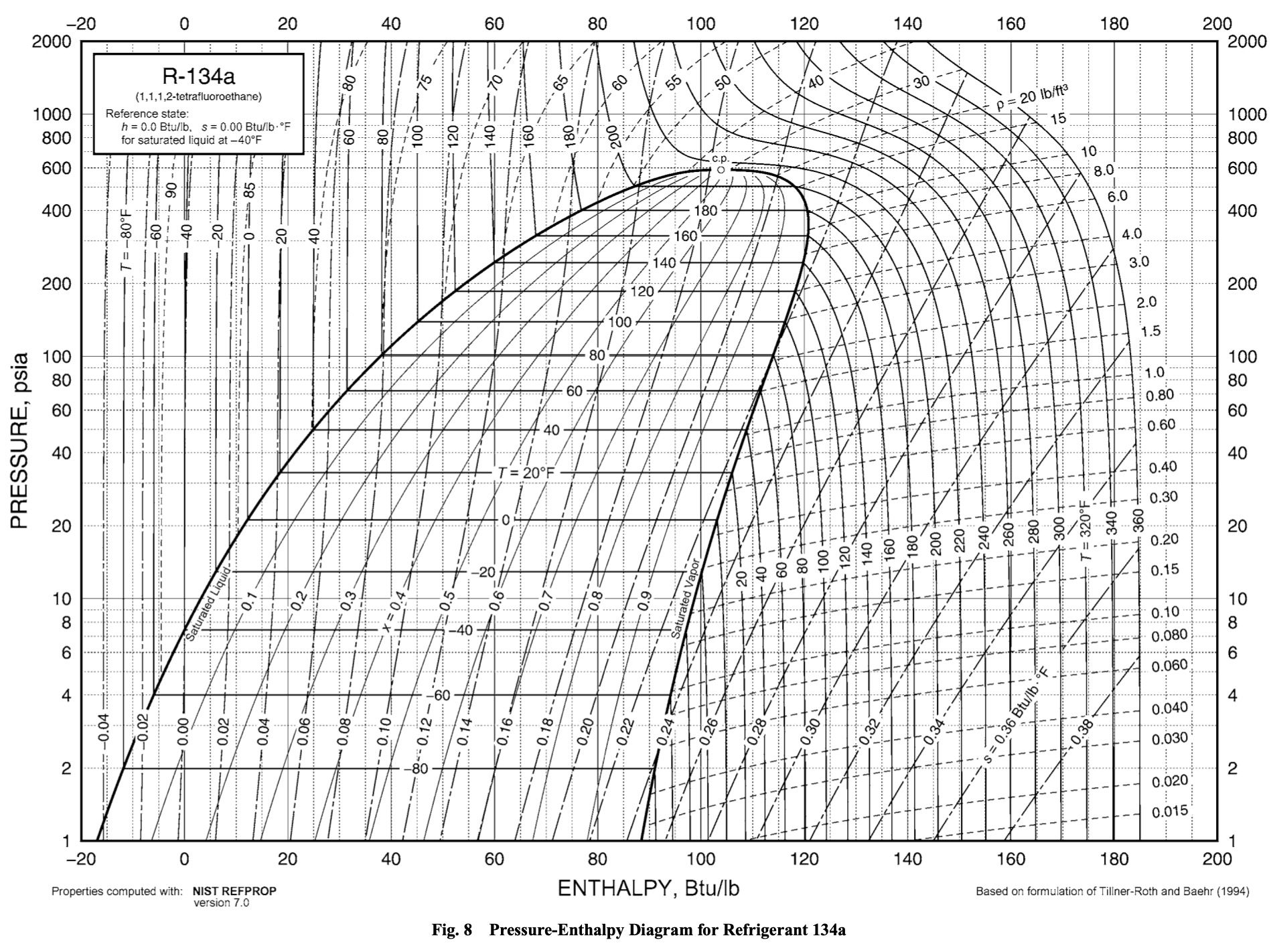
June 10, 2020 at 2:11 pm in reply to: Sealed system thermodynamics Part 2 video – Plot points #19231All the Samurai is doing is looking at the measured pressure and temperature at each point and then marking the spot on the P-H diagram that corresponds to it.
For example, look at point #1 in the R134a system shown in the video — the one right at the compressor suction. You have 16 PSIG and 47 F there. Now you take that pressure and temperature, find the spot on the diagram where they intersect, and mark it.
Here’s the P-H diagram that was used in the video. A couple things to note:
The temperature lines change drastically depending on whether you’re looking within the saturation dome or not. If they’re in the saturation dome, they’re horizontal. If they’re outside it, they’re almost vertical. That’s representing how pressure and temperature are directly related within the saturation dome, but not outside of it.
Also, pressure on this chart is shown as PSIA (PSI Absolute) rather than PSIG (PSI Gauge) which is the value we’re given. I believe the difference between these was explained in the video. To convert from PSIG to PSIA, just add 14.7 to your PSIG value. That will give you the equivalent value in PSIA.
See if you can find the spot that corresponds to 16 PSIG and 47 F (without referencing where it is in the video, of course).
Great questions! Let me lay it out for you best as I can.
1. Practical Sealed System Thermodynamics, Part 1. 19:26 into the webinar
At test point 1, 84psig: at the suction of the compressor:
Shouldn’t the superheat value be 21 deg F instead of 41 d deg F as in Webinar?Yep, using the data that the Danfoss app has now, 21 F is the correct amount of superheat there. That webinar was recorded a couple years ago, and there have been a lot of changes to the Danfoss app since then, including data table corrections. Usually these corrections are only in the range of a few degrees or a few psi, but this is a big one — a 20 degree difference. I can only imagine that there was an error in the app’s data back then that has since been corrected. Good spot!
2. When I was using Dan Foss App to do the homework, I noticed there was selection to make between “Bubble” vs. “Dew”. After doing some searching on the internet, when doing the subcooling calculation should use Bubble, and for superheat should use Dew. Can you tell me why this is so. I know what the Bubble and Dew stands for by definition. I just want to know reason for: subcooling = use Bubble and superheat = use Dew in Dan Foss App. I also know for newer hybrid refrigerant like 404A there is glide between the bubble and dew point.
The bubble and dew points are just terms for referring to either side of the saturation dome on the P-T chart. The bubble point is on the left side of the dome, referring to when the liquid refrigerant is “just starting to bubble”. Conversely, the dew point is on the right side, referring to when the refrigerant is now almost entirely vapor, with “just a few drops of dew left”.
Since subcooling takes place to the left of the dome, you should use Bubble to calculate it. And since superheat happens to the right of the dome, you should use Dew to calculate it.
The reason why that Bubble/Dew switch exists (another feature that wasn’t around back when we recorded that webinar) is because R404a is a zeotropic refrigerant. That means that it’s made of a mixture of different substances that boil at different temperatures (unlike homogenous refrigerants like R134a). And as you pointed out, there is glide in zeotropic refrigerants like R404a. Glide means that the lines within the saturation dome are not parallel with the x-axis as they are in homogenous refrigerants.
For demonstration purposes, here’s a P-T chart for R134a, showing perfectly straight lines within the saturation dome. There’s no glide in this chart, which is why the Danfoss app doesn’t allow you to use the Bubble/Dew switch for R134a.
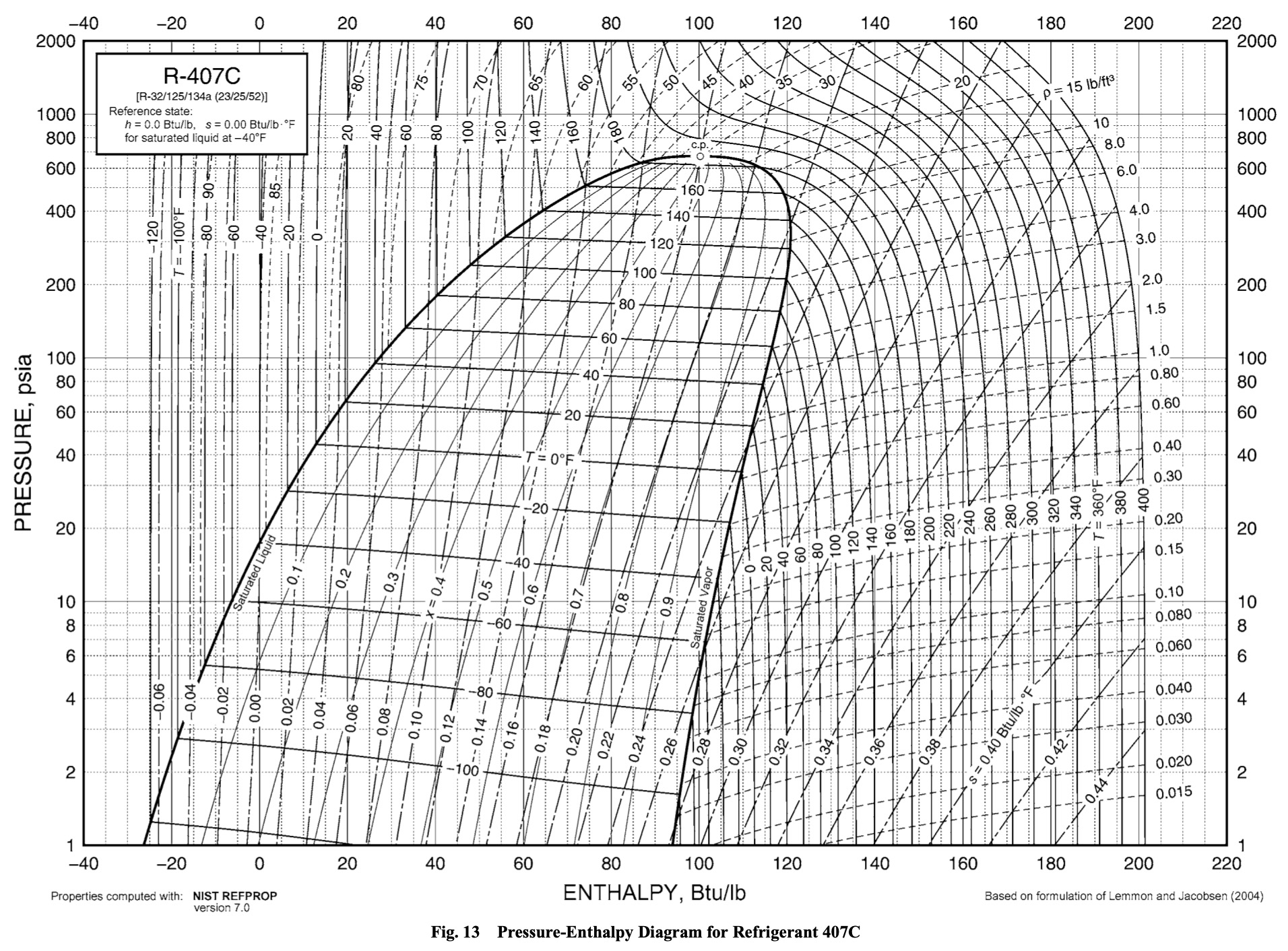
Now compare that to this chart of R407c, which has very pronounced glide:
And lastly, let’s get back to R404a, which is what you’ve been working with. The glide is much less pronounced here than for R407c, but it’s still there if you look closely.
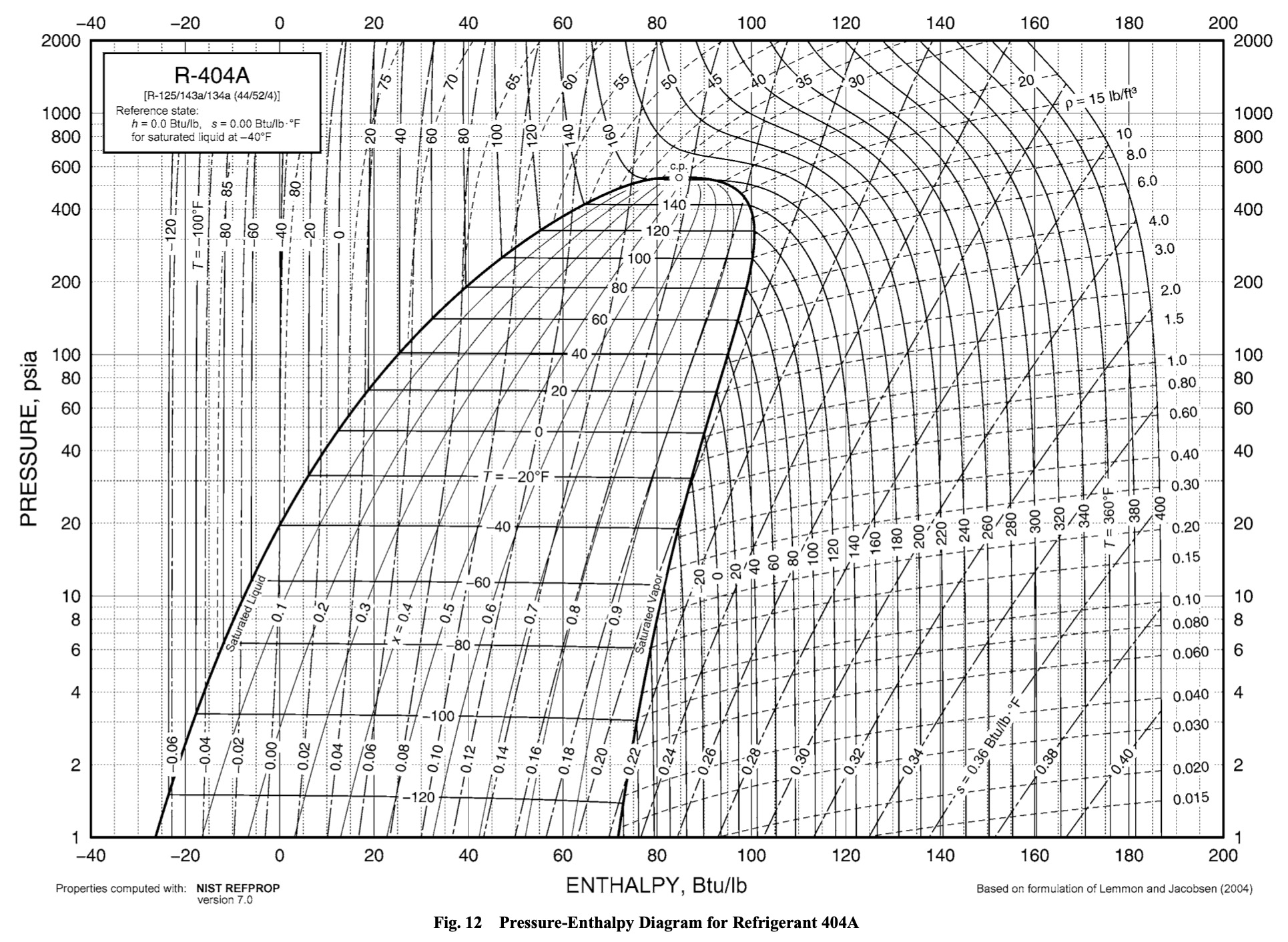
Since R404a doesn’t have very significant glide, you’ll notice that values don’t change much depending on whether you have Dew or Bubble selected in the app. But because it’s a zeotrope, the bubble and dew points are different, and so you should select the correct one depending on if you’re calculating subcooling or superheat for the most accurate results.
Great catch, Steve! There was actually an error in that question. It was supposed to clarify that it was specifically asking about timed dry. The centrifugal switch only completes the timer’s neutral in auto dry.
Thanks so much for catching that typo! The question has been clarified now.
-
AuthorPosts