Forum Replies Created
-
AuthorPosts
-
Hi Shawn,
Could you post a link to the spec sheet or Amazon page for that Sperry tester? If we can take a look at the specifications for the tester, we might be able to figure out what’s going on here.
There will be a bit more info on that — there’s a unit later on that covers using the Ten Step Tango to troubleshoot a refrigerator. However, reading schematics is not a huge focus of Refrigerators, since Fundamentals and Advanced Troubleshooting cover that much more. The Oven and Range course also delves pretty deeply into a reading schematics and using them for troubleshooting.
It’s important to remember that reading schematics is not something you need to learn on a per-appliance basis. Schematics for all kinds of appliances work the same, so once you know how to read one, you know how to read them all.
A refrigerant vapor with high boiling point won’t do no good inside a evaporator coil.
Sounds like you’ve got the right idea, with one clarification: remember that vapor does not boil — it’s only liquid that boils. Since you want refrigerant to boil (i.e. change state) in the evaporator, having refrigerant that is already vapor doesn’t do you any good. And if the boiling point is higher than normal, even the refrigerant that is liquid won’t change state as readily.
We dive into the thermodynamics of refrigeration in far, far more detail a littler later in the course, so stay tuned for that!
The condenser fan is there to cool down the refrigerant inside the condenser coil to condensate the refrigerant vapor.
Correct! So if the condenser fan isn’t running, the condenser won’t dissipate enough heat from the refrigerant, meaning that some of the refrigerant will still be vapor when it exits the condenser. In addition, more heat means more pressure, and more pressure means a higher boiling point.
So if you have a) a portion of the refrigerant that is already vapor when it enters the evaporator, and b) a higher boiling point in the evaporator, what effect will that have?
Woudn’t a weak compressor not pumping enough refrigerant be the cause of a partially frosted evap coil? I don’t get why a condenser fan would be the problem here.
Let’s take a step back to understand the concepts involved here. Could you tell me what the purpose of the condenser fan is?
How could a condenser fan cause partially frosted coil?
Scott actually spends about a minute in the Module 2 unit 2 video explaining how a bad condenser fan can cause a partially frosted evaporator. Give it another watch, and if the explanation still doesn’t make sense, let me know what about it is giving you trouble.
This is the kind of thing that the Appliantology forums are great for! At Appliantology, you can easily attach images to posts, and you can get input from other technicians as well as us. Plus, you get to flex your shiny new MST Student membership.
One of the forums at Appliantology is called The Dojo — you can find it by reading through the forum listing on the homepage. Post your schematic question there as a new topic, and we’ll help you out with it.
I see you edited your reply. Rewatch the video, and reread the text description before it in the unit. Was the problem that the board wasn’t supplying power to the damper?
Right again!
Now let’s turn this back to the damper motor. That motor is just a normal load — nothing special about it. When you read across it with your meter, just like the Samurai did in the video, what would you expect to read?
Correct!
Now what if you have that same circuit, but it only has one load in it? What voltage drop will you read across that single load?
Sure, let’s try an example to make sure you have a clear idea of voltage drop. Note that this isn’t the same circuit as the damper’s, but it doesn’t need to be. Once you get this concept, you’ll see what’s going on with that measurement across the damper motor.
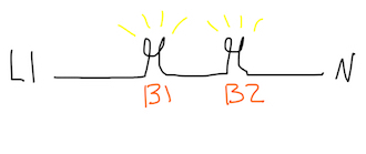
B1 has equal resistance to B2. If you use a voltmeter and measure with one probe on either side of the load marked B1, what will your meter read?
Clearly the damper was bad, but why was the control board also bad? It said 120v so the circuit was open but why did you say it was supposed to switch?
The meter was reading the voltage drop across the damper motor. You can see that the probes are placed directly in the harness for the damper. That 120 volt reading does not mean that the circuit was open — it means that the switch on the board was closed and supplying voltage. If the circuit had been open, he would have read 0 volts because there would have been no power supply.
As for why it’s supposed to switch, you can use common sense for that. Should the motor be energized at all times? Its job is simply to open or close the damper, so it should only be energized when it’s supposed to be doing that.
Note the * character in the model number provided by the manual. That’s an asterisk, and it serves as a wildcard character. That means that, no matter what character occupies the same spot as the asterisk, this manual applies to that model.
Correct, circuit diagram is yet another term you’ll see thrown around. The important thing to learn is how to identify what a schematic looks like — that lets you tell that it’s a schematic regardless of what label it has.
Service manuals don’t always use the most precise terms. What they’re calling a wiring diagram is actually a schematic—you can tell because it’s readable, not a tangled mess of lines.
-
AuthorPosts