Forum Replies Created
-
AuthorPosts
-
The short definition of an LOI is just “the thing that’s not doing its thing.” We’re not trying to conjecture about potential causes of the problem at this point — that’s getting ahead of ourselves. Right now, we just need to focus in on the load that’s not doing what it’s supposed to be doing.
Given the information from the previous two units in this case study, which load would that be?
January 16, 2019 at 9:53 am in reply to: Testing motor windings on a single phase asynchronous motor #15166In fact, here’s an image of a split-phase motor taken directly from a dryer schematic. You can see the two windings and the three terminals, like we’ve been talking about:
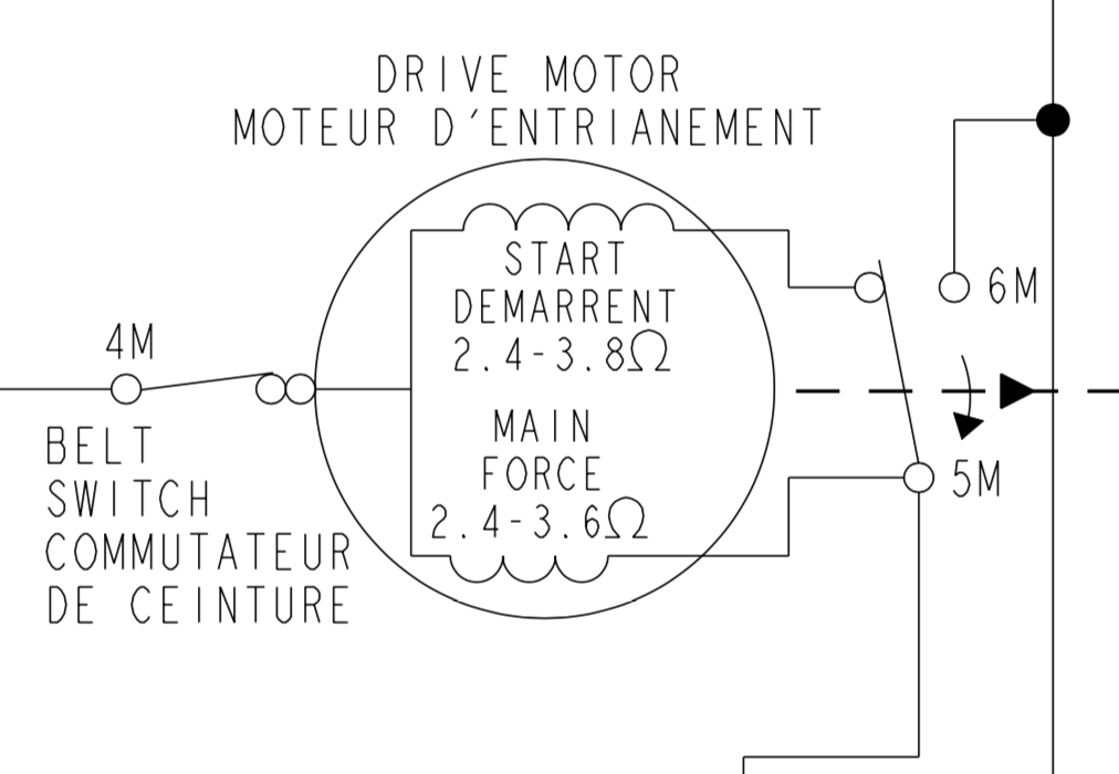
On this particular schematic, the common terminal is the one on the left-hand side of the motor. You can see that it’s connected to both of the windings (which is what makes it the common terminal).
The image also shows the centrifugal switch, which takes the start winding out of the circuit after the motor has started spinning.
January 16, 2019 at 9:11 am in reply to: Testing motor windings on a single phase asynchronous motor #15162So on a compressor motor there are three windings
No, there are only two windings on any split-phase motor — start and run. But there are three terminals, one particular to each winding, and then one that is common to both.
This is not specific to compressors. Split-phase motors are configured this way across various appliances.
January 15, 2019 at 4:04 pm in reply to: Testing motor windings on a single phase asynchronous motor #15160Here’s a helpful picture showing the windings of a split-phase compressor motor:

You can see that there are three terminals on the motor: the start terminal, the run (or “main”) terminal, and the common terminal. As you might expect, the start terminal is connected to one end of the start winding, the run terminal is connected to one end of the run winding, and the common terminal is connected to the other end of both windings.
To measure the resistance of the windings, you would simply make your measurements between all three terminals. Even if the terminals aren’t labeled, you’ll be able to tell which is which by simply comparing your resistance measurements, since the start winding’s resistance will always be higher than the run winding’s.
Just to make sure you’ve got the concept, see if you can figure out which terminal is which on the image where the terminals are just labeled as X, Y, and Z.
December 26, 2018 at 11:48 am in reply to: basic electridity question one on exam curcuit breakers pana;samd power circuit #15095Sorry for the delay in getting back to you, Phillip! Could you copy and paste the text of the question you’re having trouble with and post it here? I’ll be able to help you best that way.
There’s a tricky little thing that you have to notice. The circuits for the RR, LR, and LF surface elements are all consolidated into one circuit on the schematic. In reality, they’re three different circuits, but since those circuits are all the exact same configuration, only a single circuit is shown.
This means that each of those three elements has its own L1 to H1 contacts, and its own black jumper wire that connects to its own hot indicator light.
Make sense?
December 2, 2018 at 5:17 pm in reply to: Module 1 Unit 9. Refrigerator Defrost Systems troubleshooting without tech sheet #15028Hey, great job spotting the trick question! We were waiting for someone to do that. 50 bonus points for you! 😉
I do see how that wording is confusing, so we’ve gone ahead and tweaked it to say that you are specifically missing the diagnostic mode entry procedure, not necessarily the entire tech sheet.
Thanks for letting us know about this!
November 26, 2018 at 11:05 pm in reply to: Question #9 on refrigerator repair refrigerant cycle. #15001Anytime. Don’t be afraid to post here in the forums whenever you get stuck! 🙂
November 26, 2018 at 11:12 am in reply to: Question #9 on refrigerator repair refrigerant cycle. #14998Yes, you’re right! Refrigerant does leave the compressor as a hot vapor. If you read through all of the possible answers to this question, I think you’ll see one that reflects this.
Thanks for posting your question in the forum!
The information you need to answer question #6 is indeed in the course material. In fact, I believe it’s touched on at multiple points throughout the Basic Electricity module. Once place where the correct answer to this question very clearly stated is in the text of unit 3 of Basic Electricity. Review the material there, and you’ll find what you’re looking for.
And in the future, please don’t hesitate to post questions in the forum when you’re stuck! We’re always happy to point you in the right direction.
Yes, exactly right! The reason that our LOI is the electrode is because, in this troubleshooting scenario, we hear a spark being generated, but it’s not coming out of the electrode like it should. As you troubleshoot further, you’ll figure out whether this is because the electrode itself is defective, or whether there’s some other, underlying cause.
Let me know if you have any more questions!
Not quite — the spark lead shown on the schematic is just a connector between the spark module and the sparker wire.
Your LOI is supposed to be the “thing that’s not doing its thing”. There’s a specific component whose job it is to emit a spark into the gas, igniting it. If you’re still not sure what it’s called, I recommend you rewatch the video in Module 7, Unit 3 on spark ignition systems.
There’s a specific part whose purpose is to deliver that spark to the burner. It’s at the end of the sparker wire that comes from the LF burner’s spark module. That’s the part that’s not doing its job, since it’s not igniting the gas that we smell coming out of the burner. Can you identify what that part is?
You don’t need the wiring diagram at all to answer this question — in fact, it will tend to mess with you more than help. As usual, the schematic has all the answers you need.
Let’s do a thorough load analysis of one of the hot indicator lights. The schematic shows two different paths that Line 1 can take to get to the hot indicator light.
The first path is through contacts L1 to H1, and then through the black jumper wire. The jumper wires are hard to notice on the schematic, but they’re there — look for the label BK(J). When contacts L1 to H1 are first closed, thereby supplying voltage to the surface element, voltage is also supplied to the corresponding hot indicator light through the black jumper wire.
The second path for Line 1 is through the light’s bimetal switch. This is a switch that closes once the corresponding element gets hot enough. Once this bimetal has closed, the hot indicator light no longer needs L1 to H1 to be closed in order for it to stay lit, since it’s now receiving Line 1 through the bimetal. The bimetal will stay closed until the surface element has cooled down enough for the bimetal to open.
And of course, the hot indicator light is simply hard-wired to L2, so nothing tricky there.
Hopefully that load analysis helped clear up how the hot indicator light receives L1. To review: At first, the hot indicator light receives L1 through the same switch that supplies L1 to the surface element. But then, once the element has heated up enough, the hot indicator light also receives L1 through its corresponding bimetal switch. And thanks to this bimetal switch, the light can stay on even after the element has been switched off, at least until the element cools down.
If anything still doesn’t make sense, let me know.
The answer is True. You will probably never be in a situation as a technician where you have to measure DC current. DC voltage you will absolutely measure many times. But not DC current. It’s simply not a diagnostically useful measurement.
-
AuthorPosts