Forum Replies Created
-
AuthorPosts
-
when you have a working microswitch and its normal State and a live 12 volt circuit. Answer is youre reading 12 volts DC on the normally open and common terminals.
What you need to know is right there in the wording of the question — the premise is that you’re measuring from the normally open terminal to the common terminal. Since the switch is in its normal state, you know that the normally open terminal isn’t connected to the common terminal. Therefore, you would read a voltage difference of 12 VDC between the two points.
Hi John,
Excellent question! You actually caught a typo in the text — it should definitely say “warm liquid” there. Great catch!
By the way, we go into much more specific detail about the thermodynamics of the refrigeration cycle in Module 3, so look forward to that! I think you’ll enjoy it.
Hi Abe,
The point of this question isn’t to jump straight to theorizing about the root cause. What we want the student to do is simply recognize that, when you have freezing in the fresh food compartment of a single-evaporator unit, it’s always because too much air is flowing from the freezer into the fresh food compartment. It is, therefore, the air distribution system that’s not behaving how it’s supposed to.
In a real troubleshooting scenario, you would then move on to finding the component that’s causing the problem. It might be one of the parts of the air distribution system, or it might be part of the control system, as you pointed out. But that goes beyond the scope of this question.
Hope that makes sense!
July 17, 2018 at 8:03 pm in reply to: APPLINCE MOTORS MODULE 8 VARIOUS FREQUENCY DRIVE SYSTEMS #14646Hi Papa John,
Sorry for the delay in getting back to you! Team Samurai was out of the country for a little bit, but we’re back now and getting things rolling again.
While 2 is the correct answer for that question, your reasoning isn’t quite right. And this is partly to do with the wording of the question being a little confusing. It said “energized”, when what we really meant was “polarized to do work”. I’ve changed the question to clear this up.
If you recall from the video on electronic commutation, it’s not enough for a motor winding to just have current flowing through it. The current has to be flowing in the direction that will create a properly aligned magnetic field to push on the permanent magnets in the rotor.
As shown about 14 minutes into that video, even if all three windings have current flowing through them, only two of them will be polarized correctly.
Thanks for asking!
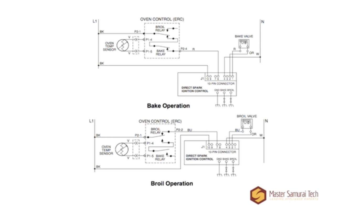
Sure thing! Here are those two images. You can just right click on them and download them to your computer.


Yes, that’s correct that the ice would be absorbing the heat in that case. However, something else to notice is that, in this theoretical situation, you would not be able to freeze anything. The coldest that you’re able to get something with ice is 32 F. Think about putting ice cubes in a glass of water. If you really stuff the glass with ice, the water would get close to 32 degrees, but it would not actually freeze.
If you want a really thorough explanation of thermodynamics in refrigeration, I recommend you watch our series of webinar recordings on the subject. You can find them either in the bonus module in the Refrigeration course or on the Webinar Recordings Index page at Appliantology.
Absorbing heat and chilling the air are really just two sides of the same coin. You can’t have one without the other. In order for the refrigerant to absorb heat, it has to extract that heat from the air, thereby cooling it. In order to chill the air, it has to absorb the heat from the air. That heat won’t just go away by itself!
Let me know if that’s still not clear.
Hi Jim,
You’re right, that was a typo! I’ve corrected it and rephrased that whole paragraph to make it clearer.
Thanks for letting us know about this!
Keep in mind the rule about schematics vs. wiring diagrams: wiring diagrams show the circuit as a human sees it, whereas schematics show the circuit as electricity sees it. Because of this, it’s difficult (if not impossible) to identify EEPs using a wiring diagram, since EEPs are all about the way electricity sees the circuit.
Trust the schematic on this one. That table in the technical data section is just showing what the specs are for the different components — it’s not enumerating exactly how many there are of each in the unit.
Also keep in mind the wording of the question. We want to know how many elements there are in each oven, not how many there are in the unit as a whole.
Let me know if anything is still unclear!
Yes, that’s correct! Since these are parallel circuits we’re talking about, each bulb has its own path to line and neutral, so one is unaffected by the state of the other.
We don’t have a particular brand/kit of wire connectors that we recommend. However, there are some types of connectors that we do recommend having on hand (and some we recommend against!).
For wet environments, wire nuts that already have silicone grease inside them are great. That way, you don’t have to worry about applying the grease yourself after the fact to make the connection waterproof. Click here for an example of these.
For environments that aren’t wet and aren’t super hot (you’ll want porcelain nuts for hot places), we’ve had the best results with crimp-on bell connectors. These actually make for a better, longer lasting splice than the standard screw-on plastic wire nuts. Click here for an example of them.
You’ll still want to have some of the screw-on type around, since you don’t always have the room to crimp on a bell connector.
What we definitely don’t recommend are butt connectors like these. They’re a hassle, and they don’t make for very reliable connections, nor are they as reliably waterproof as the silicone-filled nuts mentioned above.
Hi Phil,
Could you let me know which unit in the course makes reference to that webinar?
Sam
Hi Philip,
In units that have them, the cold control is part of the air flow system, because part of its job is to switch the evaporator fan motor on and off. So yes, repairing a stuck cold control would be part of restoring proper air flow.
Yes, you got the math exactly right!
One small correction: it would be 1352 watts, not volts. Remember that “P” in the equation means power, so we’re solving for units of power (watts), not units of voltage (volts).
Great work!
-
AuthorPosts