Forum Replies Created
-
AuthorPosts
-
That reactor is just a filtering device. It’s there to ensure that no power spikes or other potentially harmful noise on the line reach the main control or the inverter — hence why it’s in the power supply for both.
so if im able to measure line voltage when the door lock switch is open that means that MOTOR CONTROL UNIT in this case would act like a wire creating a path back to the lock switch.m i correct?
If the door lock switch is open, there’s no way for line to reach the motor control unit. So no, there’s no possibility of reading line through the motor control unit. That wouldn’t really be a possibility anyway, considering how these boards work.
the above question is refering to you last answer on #24553 So for the door switch in the first video, you would measure a small DC voltage across it when it’s open. For the door lock switch, you would read line voltage across it when it’s open.
Yes, correct on both counts!
so on you first video at 5:58 minutes your showing check points
pin 3 to 4 goes to the locking solenoid, pin 6 to 4 goes to the unlocking solenoid
but pin 1 to 2 goes to where?what does it energize and why its using 12vdc rather than 5vdc?This is a slightly different lid lock setup from the other schematic we were looking at. In this one, it looks like you have two switches: one between pins 3 and 4, and the other between pins 6 and 4.
Pins 1 and 2, on the other hand, are for powering the locking solenoid. That’s why it takes 12 VDC — that’s a very typical voltage for DC loads.
2.your first video at 8:00 minutes showing a diagram and just below the lid switch there is a little circle pointing a dashed line towards the lock switch what its function ? ther is also a writing SINGLE 40 MS PULSE TO LATCH OR UNLATCH,beneath it to the left what does it mean?
The dashed line is just there to show that the circle (which is labelled as the door lock solenoid) opens and closes that switch. And the text about the pulse is telling you that it just takes a 40 millisecond pulse of power to actuate the solenoid.
also on J15 CON PiN 2 there is a line tiped with an arrow pointing at a piece of writing LID SWITCH INPUT,is it a signal line to the board letting it know when the door is closed? if so,as i gather from the diagram it send ac voltage(but the NEUTRAL SIDE RATHER THAN LINE) to pcb in order for the pcb to sense if the door i closed or open, m i correct? meaning when the lid switch is closed the pcb will sense that ac neutal , is it even possible to sense neutral?i guess it is since its an alternating current traveling back a forth
Yes, neutral sensing lines are very common, and that’s exactly what the board is doing here. It’s sensing the presence or absence of neutral, by which it can tell if the switch is open or closed.
on your 5th vid lesson on the schematic there seems to be an overload on the right side of the drain pump m i right? if so,why does it need to have an overload for?is there such a thing as a drain pump with an overload or my interpertaion of that symbole is wrong?
Yep, that looks like a bimetal cutoff. It’s probably there in case the pump gets jammed and starts drawing locked rotor current. That will cause the bimetal to get hot, and then it will open the circuit and protect the pump.
secondly you mentioned that after we verify with a voltage test the the traic is indded good we can ohm out both the drain pump and the inlet valve,wouldent a volt test be preferable over the ohms test (as ohms test lie)? can we enter the service mode and carry out unit opertion and check for 120vac to the pump or inlet valve cant we?
If we confirm that the triac is good, then we know that the board is capable of supplying line. In fact, in order to test that triac, we probably would have been in test mode. So doing an ohms measurement here is not a bad idea. Ohms measurements are fine to do, as long as they’re not the only test you’re doing and you’re applying them intelligently.
thirdly if we have 0v across VCH7,3 and VCH7,1 it still dosent mean we have a bad inlet valve but if we do have 120v across the above mentioned and at the same time the valve isent operting it then means we should supect the and make a continuity test m i correct?
If the valve is receiving both line and neutral and still not running, then that basically proves that you have a bad valve right there. You could do a continuity measurement as a confirming test, but it’s not really necessary.
and last,on the 5th vid lesson on the schematic on the top left just below the BLDC motor there is a little circle with the letter T inside it what does it represent?
That’s the tachometer — the device that detects if the motor is rotating and reports it back to the board.
as regerds the door switch and door lock,as i undertood when you select a cycle the door switch tell the pcb the the door is closed and once the main pcb sense that the door is closed it energizes the solenoid and lock the and when the cycle is over it enrgizes the unlock coil so we can open the door mi i right?
same deal with the lid switch?
having gone through all the videos in this a few times unit and i still realy dont understand how i actualy check the lid lock/door lock? please can you explain to me in more detail how to test them?Yep, you’ve got the sequence down. As for checking the switches, a simple voltage test would do it. Just like any switch, you should read supply voltage across it if it’s open and no difference across it if it’s closed.
So for the door switch in the first video, you would measure a small DC voltage across it when it’s open. For the door lock switch, you would read line voltage across it when it’s open.
1.on your first vid lesson at 9:30 minutes your showing a schematic so if i were to check for voltage across PK 1 which is line and DL3-2 or any other point after thise pilot switch AND THE PILOT RELAY on neutral IS STUCK OPEN would i read 0 ACV? just ou of curiousity will the inverter board act like a motor winding in case the neutral is open and the windings serve as a wire leting line voltage extend up to this break thus reading out only 0vac?i mean how electrons see it as you explained in one of you other lessons that when the neutral is open the line voltage wil be present up to the point of the gap is it the same with the inverter circuitry?
If you have an open neutral and you try to take a voltage measurement with a loading meter, then yes, you would read 0 VAC. On a non-loading meter, you would probably read some amount of ghost voltage. You would not have anything feeding through the inverter circuitry for many reasons. For one, an open neural means the inverter doesn’t have a valid power supply, so none of its electronically controlled switches would be closed. For another, an inverter doesn’t just serve as a simple switch that passes line voltage on to the motor. That voltage gets rectified and electronically commutated, so you can’t treat it as you would a simple switch.
2.if we already have door switch leting the pcb know the the door is closed why do we need to have lock switch?
Those switches serve different functions. The door switch tells the board if the door is closed. The door lock switch, on the other hand, makes or breaks the line supply to the inverter and all the other loads. So those two switches serve different functions.
3.under the connector UIP3 PIN 1 i ground and pin 3 i -7v traveling to EBP3 WHY IS IT -7 RATHER THAN +7? in other words why is it negative voltage there? it seems weird to me
DC voltage can be either positive or negative. Functionally, +7 VDC and -7 VDC work the same — it’s going to push the same amount of electrons through that circuit. It’s just that -7 VDC is 7 volts more negative with respect to ground, whereas +7 VDC is 7 volts more positive with respect to ground. For whatever reason, they have specified negative voltage here.
4.on your 3th vid lesson where tou check the continuity of the door switch, was it possible to do a voltage check insted of continuity and if it is how ?
If he had been able to get his leads onto the wires, then yes, a voltage measurement would have been possible. But to do that, he would have needed to leave the connector in place and get the meter probes onto the wires through the back of the connector, which doesn’t look possible in this case. So, due to practicality, he opted to disconnect the harness and do a continuity measurement.
5.what are those 2 little squares below DCS3 conector represent? and what are the arrow facing downwards with the inscription DOOR SWITCH OUT?
there are another arrows,one under connector DI6 PIN 3 with the inscription switch position and the same on the top right ther are another 2 arrows one is labeled presence sensor out and the other detegent level sensor out,what are thos arrows?Those squares are indicating that the door switch is supplied with DC voltage. You can also tell that from the “Vcc” written below pin 1. If those squares were not there, it would look as if line voltage were going through that switch, which is not the case.
The arrow is indicating that the board is monitoring whether voltage is present at DCS3-3 and using that to determine the state of the door switch. Similar principle with the other arrows you mentioned. The schematic is using those to show where the board is receiving a signal from those sensing devices.
Yes, that’s correct. When the flame sensor is closed, you have L1 on either side of the main coil, meaning it won’t run. So the flame sensor is shunting the main coil.
If you look at the schematic at 52:44, you see the exact same thing happening, except that you have neutral on either side of the main coil instead of L1. Same effect electrically, just with the power supply reversed.
Hi Zachary,
Here’s the circuit:
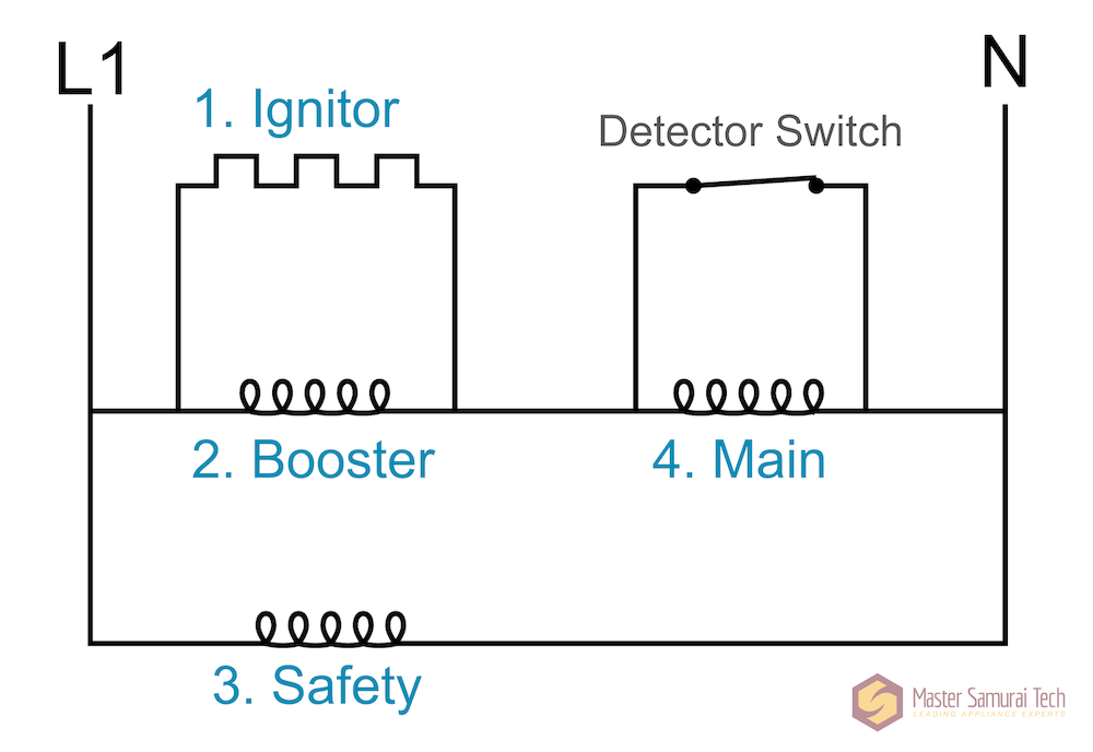
On your last attempt, you had said that all four loads would drop 120 volts. That’s correct for some of them, but at least one of the loads does not have 120 volts of voltage drop. The key is the detector switch. Can you tell me what the function of that switch is in this circuit?
November 12, 2022 at 10:51 pm in reply to: How does the PTC stay out of circuit after motor start #24409The key here is that the PTC doesn’t go to infinite resistance — just very high resistance. So it has a tiny amount of current running through it, which is enough to keep it hot and its resistance high. And since its resistance is so much higher than the start winding that it’s in series with, it drops essentially all of the voltage, so the start winding does no work.
Relatively simple, no? Let me know if it doesn’t make sense.
Is it the same as setting up the hotspot to see if the wifi module has connectivity or is there another way to test RF using a measuring device?
Yep, you could either use the hotspot technique, or you could use an EMF meter like we talk about around 39:20
Yep, the voltmeter is connected in series with the diode.
And I should amend my previous response — you actually should to read the full voltage across a good high-voltage diode. It should be a few volts less than the supply voltage. If you read the full 9 volts, that actually indicates a failed diode.
Here’s a video showing the diode test:
-
This reply was modified 2 years, 8 months ago by
Sam Brown.
You’re looking for voltage difference in this test, not voltage drop. And the reason you switch your meter leads is because you want to measure the voltage difference when forward biased vs when it’s reverse biased. When you measure it forward biased, you should measure no voltage difference, and when it’s reverse biased, you should measure the full voltage supply as the difference.
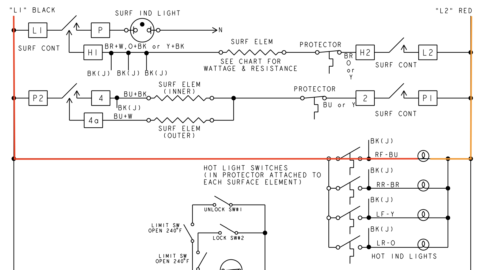
Here’s a markup of the hot indicator light on the schematic that should clear things up:
Let me know if you’re still not clear on the answer to question 3.
how can i actualy measure the frequency of the inverter board? besides does it even nessecary to do that or a test of (pmw)VOLTS that the main pcb is sending will suffice in order to check if both the inverterboard and the main pcb is not out of kilter?
As I mentioned previously, you can measure the PWM signal using a multimeter on the DC setting. You’ll read the average of the square wave, but that’s good enough to tell that the main control is trying to communicate with the inverter board.
The inverter’s output to the BLDC motor is a little trickier to measure, since it’s a three-phase power output. You need specialty equipment to precisely measure it. You can use a standard multimeter to measure the voltage and frequency on each of the three phases relative to each other, but this is only a qualitative test. This post at Appliantology explains more.
We have a webinar at Appliantology that describes how PSC motors work — click here to watch it.
why are the shaded pole motor not efficient?what makes them inefficient compared to the PCS that use a capacitor? and how does this inefficiency affect or impair thier oparation?
Because the shaded pole part of the motor is essentially a start winding that’s always in the circuit. That uses unnecessary power and reduces efficiency.
ok,so how is the speed of the AC asynchronous determined ?
Based on the physical construction of the motor — how the windings are wound, things like that.
secondly can you explain the differnce between DC BRUSH MOTOR AND AC BRUSHED MOTOR? if both usd carbon brushes do they work the same way?how do can i tell them apart? you didnt talk pretty much about the ac brushed motor
They do work essentially the same way. In fact, there exist “universal motors”, which are brushed motors that can run on both AC and DC. We don’t talk about them very much because you never encounter them in appliance repair, though.
-
This reply was modified 2 years, 8 months ago by
-
AuthorPosts