Forum Replies Created
-
AuthorPosts
-
you said that the main pcb sends PWM signal to the inverter board what kind of signal is this and how can i messure this signal with my multimeter? in addition,how is all this inverterboard and BLDC MOTOR related to frequency ? i must have missed some details along the way..
The PWM signal is a 5 VDC square wave. That means that it’s a series of DC pulses that alternate between 5 VDC and 0 VDC. The frequency of the signal is determined by how long the pulses of 5 volts are compared to the pulses of 0 volts.
This signal is received by the computer chip on the inverter board, which interprets the signal and decides how fast to run the BLDC motor based on it. The longer the 5 volt pulses are, the faster the inverter will run the BLDC motor.
You can measure it by doing a DC voltage measurement with your meter. However, note that you will read an average of the 5 VDC square wave. That means that you’re not going to see it alternating between 5 and 0 volts in real time. Instead, you’ll see an average of the voltage, usually somewhere between 2 and 3 VDC. The higher this average, the faster the main control is telling the inverter to run the motor.
furthermore,you pointed out that the inverter board are getting line voltae which is 120 AC and converts it to 170 dcv and the igbt switched invert this DC voltage back again to by opening and closing in a certain order so my question is why taking an ACV convert it to DCV and back again invert it by the igbt in other words,why should the converter board first convert ac to dc AND then invert it for the motor to ac when we have ac power supply in the first place that could be left intact doing the opening and closing stuff with the original line supply?why is it necessery to first convert to dc and back again to ac if we already have acv ready at hand?
You’re right that it seems counterintuitive, but it’s really not. The inverter isn’t turning the line voltage supply into DC just to convert it back to AC. It’s turning it into three-phase AC. In order to do that, it first needs to convert the single-phase 120 VAC power supply into DC, then convert that DC into three-phase AC using its computer-controlled switches.
why is the system entiteld Variable Frequency Drive? has it something to do with the PWM signal being sent to the inverter in order for it to control motor’s speed? up to now i just cant figure out how frequency play a part in all this vfd system
“Variable Frequency Drive” or “VFD” is a term used to refer to the entire system covered in the unit. The PWM signal, the inverter board, and the BLDC motor are all components of the Variable Frequency Drive system.
you stated that an ac synchronous motor is keyed into the frequency of the power lines(60hz) do it mean that the speed of the motor is solely controled and dependent on the frequency?
Correct — there’s a direct relationship between the frequency of the AC power and the rotation of a synchronous motor.
and as for brushless DC motors’ speed is the same deal but with a variable speed thanks to the inverter board decoding the PMW into AC POWER with other frequencies?
The speed of a BLDC motor is determined by the frequency of the PWM signal sent to the inverter, but it’s not in the same direct way as a synchronous motor. The inverter receives the PWM signal, and then determines how quickly it should run the BLDC motor based on the frequency of that signal.
secondly as i figured out,all types of motors’ SPEED is indeed determined by frequencies m i right?
Not all types of motors — asynchronous AC motors, like the split-phase motors commonly used as dryer drive motors, do not rely on the frequency of their power supply to determine their speed.
first i want to take my hat off to you and tell you im realy imperssed at the lessons, just owesome ! second you have stated a couple of times that when checkig NTC SESORES OR RDL voltage drop is prefered over ohms vs temperture so suppose i look through the tech sheet and the voltage drops is not listed in the chart of specs is there any way to work out the voltage drops i should get in some spots on the chart so i can go on and follow up with the voltage drop test or if this data is omitted i have to proceed with a test of ohms vs tempertur ?in other words in case there are no voltage drops on the tech sheet chart what should i do?
Glad you’re enjoying the coursework!
Voltage drop measurements are preferable if those specs are provided, but if they’re absent, then yes, simply proceed using the ohms chart instead.
as regards the thermocouple how can i test them? having worked in the solare system and boilers industry iv run into them many times and also replced them iv notices that they are connected to a pcb runing a motor to pump water into the solar panel in cases when the solare panel is positioned above the boiler i know its some type( a pair of long wires attached together) of sensor could it be a themocouple?
Thermocouples aren’t used much in household appliances — NTC thermistors are pretty much always used for situations where temperature measurement is required. Thermocouples are different technology from thermistors. A thermocouple is two wires made of dissimilar metals which produce voltage proportional to the temperature they are exposed to. So if you did encounter a thermocouple, you would need to have a spec chart showing what voltage to expect at which temperatures.
and third why if the ntc sensor is shorted the micom will messure very low voltage at the junction point of(R2)?where has all the voltage gone?
If a thermistor is shorted, there’s going to be no voltage drop across it. So that would explain why you would measure no voltage (or only a tiny amount of voltage) across it.
Most pressure sensors work by sending a frequency signal to the main control board. I actually have a blog post all about this at Appliantology — you can click here to read it. That should explain things pretty well.
YES IT DOES but does it mean that if i were to make sure and check if the pcb was actually sending that 5v to the thermistor would i pull out that thermistore harness from the board and messure pin accross pin 10 and 12 on the board itself to check for 5v or would i be more concerened with voltage drop as you mentioned above and leave the thermistore harness contected to the board and go ahead and insert my probs somehow(if feasible) to pin 10 and 12 in (while the thermister is still connected to the board) in order to measure the voltage drop?
besides as long as the appliance is pluged in getting power from the receptacle does the pcb sending that 5v output at all times i mean nonsonstop ?We are almost always solely concerned with the voltage drop across the thermistor. The control board is constantly sending 5 VDC to the thermistor as long as it has power, and that rarely fails. Out of spec thermistors are far, far more common.
secondly since if i were to check the themistor separatly i can do that by taking a mesurement of resistance in a certain temprture and compare it to the specs.
if i pull out the themistor’s harness and measure the pcb’s pin 10 and 12 for 5v and and check if the themistor resistance in a certian temeture comply with the specs it mean that every thing is ok and operational as far as the thermistor’s conncerned.
i other words would it be necessry to check the 5v the pcb via pins 10 and 12 with my multimeter to verify that the pcb is doing what its supposed to be doing?If you wanted to be really, really, thorough, yes, you could do this. But measuring the voltage drop is almost always the better test to do, not to mention the easier one. It’s a more reliable test than resistance, doesn’t require you to disconnect the thermistor, and confirms that the board is sending the 5 VDC supply as a part of the test.
thirdly why there are some ports on the pcb has 12v pin and some of them dosent(for example FZ-MOTOR FAN,R-FAN MOTOR,ICE PIPE WATER HEATER) why do the have another pin labbled 12v and FZ SENSOR dosent?
The freezer thermistor does not use a 12 VDC power supply. It just takes 5 VDC and DC ground. The other loads you mentioned run on 12 VDC, because they are loads that are meant to do work. They are not sensors.
You’ll notice that each of the fans has a third wire other than 12 VDC and ground — the one labelled FG. That’s a speed signal wire, which is an output from the fam and an input to the board, telling the board how quickly the fan is running.
You are correct that some inputs to the board require an output from the board in order to function. It sounds like you’re thinking of thermistors in particular.
A board outputs a small DC voltage to a thermistor, and then it measures the voltage drop across that thermistor. So in this case, the voltage supply is an output from the board, and the voltage drop is an input. In practical terms, we usually treat thermistors purely as inputs, since that’s how they operate functionally. We’re interested in that voltage drop, not the initial voltage supply from the board.
As for the second question, you identify the input/output that you want to measure by looking at the schematic and the board pinout (if present). For example, if we’re interested in checking the freezer thermistor in this Samsung refrigerator, we would first identify it on the schematic:
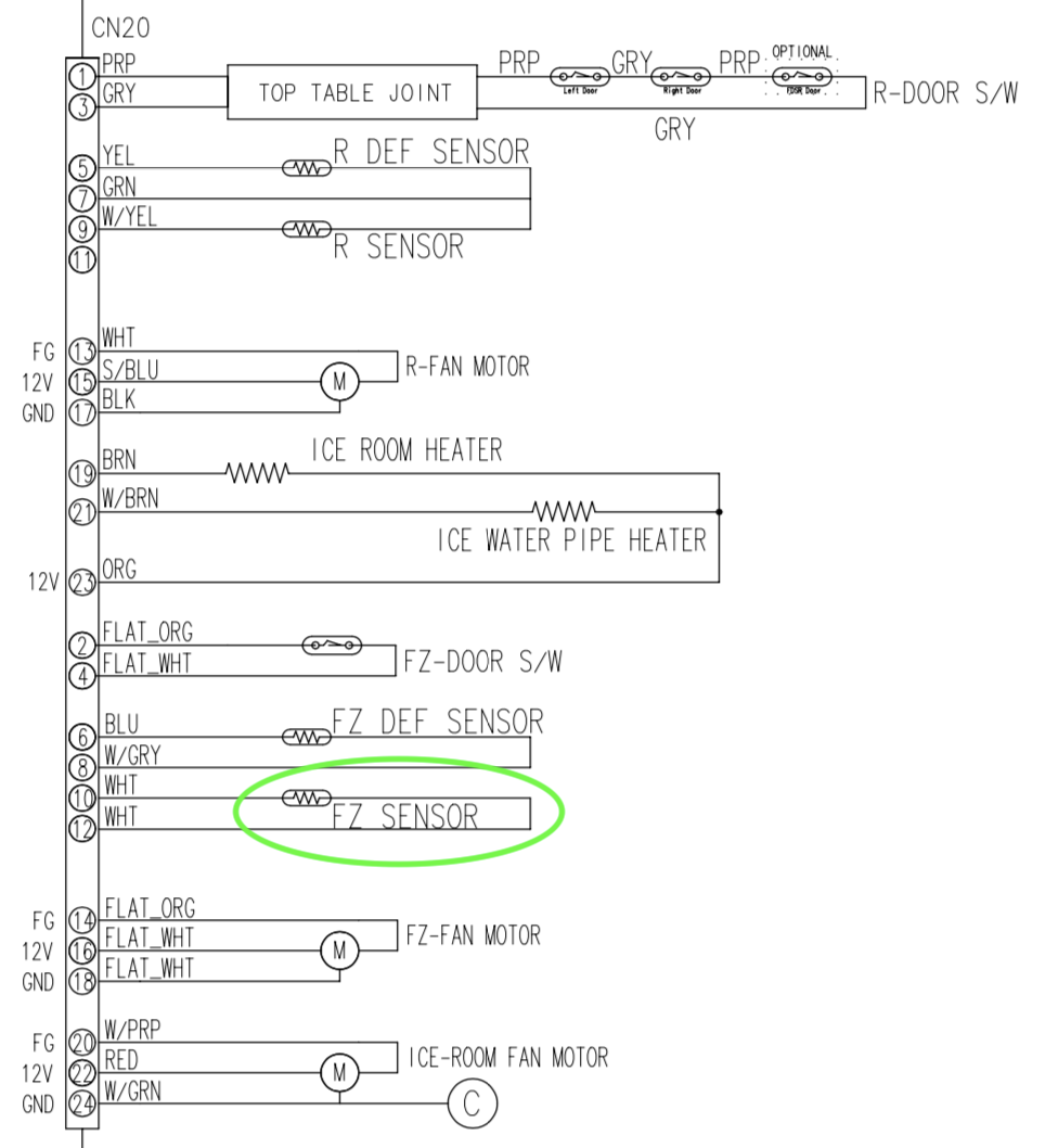
And if we need help to locate the connector where we would make that measurement, we can use the board pinout:
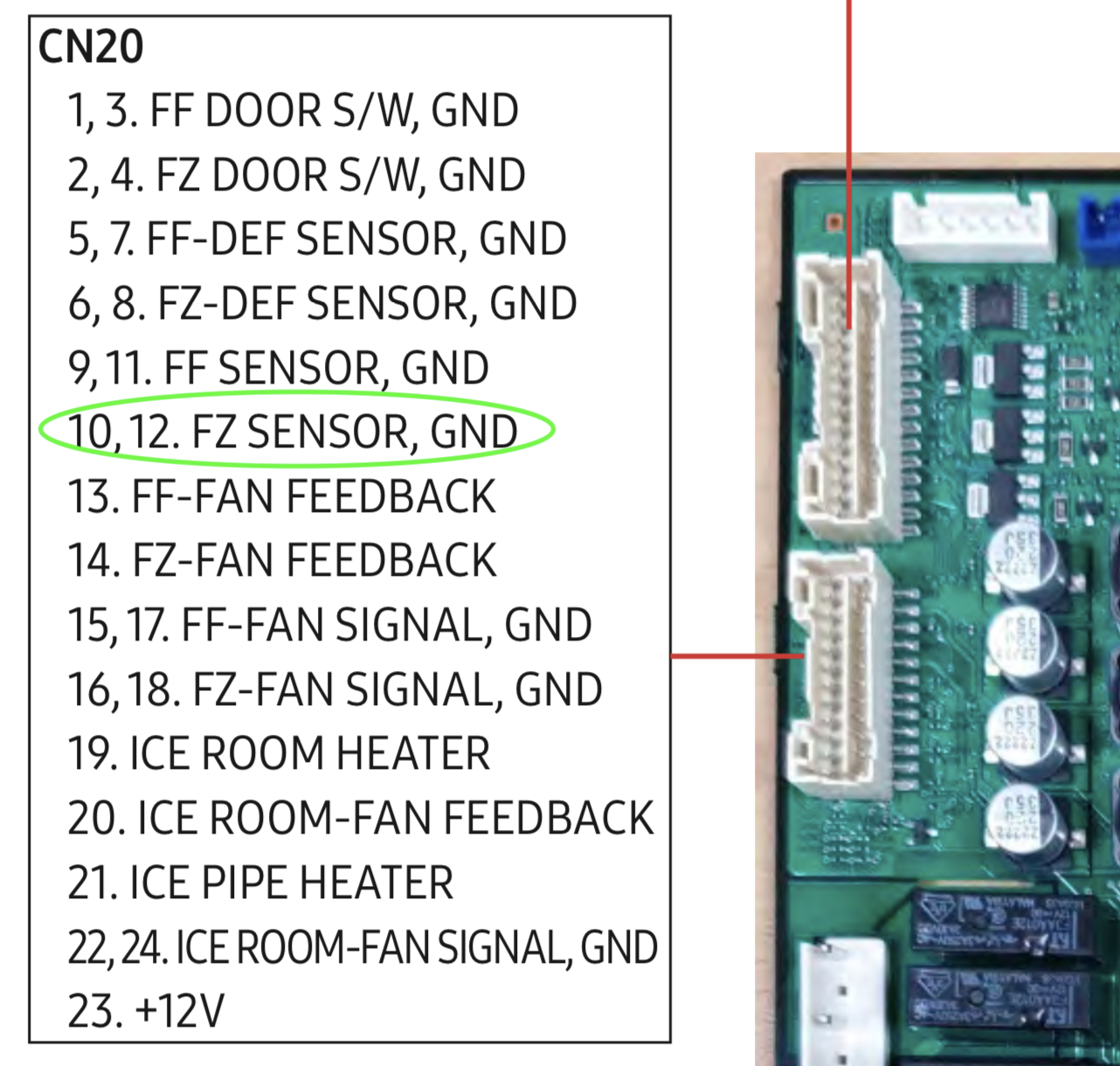
Pins 10 and 12 on connector 20 are our test points, simple as that.
Make sense?
Without getting too much into the weeds, it all has to do with those computer-controlled switches that the inverter board uses and how the algorithm decides to operate them.
First, remember that the inverter board rectifies the 120 VAC input it receives into DC. Then it takes that DC voltage and, using those software-controlled switches, it inverts the DC into three-phase AC. The voltage of this newly-created three-phase AC voltage depends on exactly how long the board keeps each of those switches closed at a time. The longer each of those switches stays closed over a particular stretch of run time, the higher the voltage will be.
That’s a very broad-brush explanation, but it’s about as particular as we need to get as appliance techs.
As I understand it, if the condenser is at room temperature the compressor is bad because there’s no compression.
When you measure a very low condenser split like that, it always indicates a sealed system problem of some kind. Yes, it could be a failed compressor, but it could also be a number of other sealed system failures, such as a refrigerant leak.
As for why you got that small of a split on a machine that was still marginally cool, that would seem to indicate that you caught a problem that was just beginning to manifest.
It depends on the specs of the pressure switch in question. We always make measurements with comparison to specifications. Could you provide the model number you’re talking about so we can take a look at the particulars?
June 8, 2022 at 7:50 pm in reply to: Module 4, Unit 8, Part 4 Ten Step Tango Refrigerator Workshop #23851When it comes to loading down, you don’t confirm it by taking a voltage measurement. Instead, you disconnect DC loads from the control one at a time until the control begins operating normally again. Whichever one had to be disconnected to restore proper operation is the bad actor.
Make sense?
Ok wait I think I just answered my own question.
Pretty much! Technically, the defrost heater is “running”, but as you said, the watts it produces would be so minuscule as to be negligible.
When you do an amps measurement on that circuit, you’re going to read the total circuit current. In other words, the amps you read at the defrost heater will be the same that you find at the evaporator fan. The big difference is in their respective voltage drops: the defrost heater will drop almost no voltage, while the evaporator fan will drop almost the full 120 VAC supply voltage.
Make sense?
All 4 possible positions of the 3-way valve are the same, regardless of the evaporator configuration. How exactly these positions are used and when depends on how the control board is programmed. A TDM system still has the same 4 positions that a parallel one does.
Let me know if anything still doesn’t make sense.
Yep, you’ve got it exactly right! Choose three adjacent keys and repeat the 1-2-3 sequence until you enter service mode.
Saturation occurs in the Evaporator @ 41 F. 210 – 41 = Superheated 169 F.
This is where you’re going astray. The compressor divides the high side and the low side of the sealed system. Once you’re measuring at the compressor discharge, you’re dealing with radically different pressures compared to what you were dealing with in the evaporator: 312 psig vs. 84 psig.
The saturation temperature changes with pressure. If you enter 312 psig into the Danfoss app, you’ll see that it corresponds to a saturation temperature of 120 F. That’s the temperature you need to calculate your superheat from.
If that makes sense to you, let me know what your estimate of the superheat would be now.
Hi Richard,
The purpose of the Saturated, Superheated, Subcooled spaces are for you to identify which of those three states the refrigerant is in and give the degrees of superheat/subcooling, if applicable. Is the refrigerant at saturation at that point in the system? Just put a check mark into the saturation spot and leave the others blank. Is it superheated? Put in how many degrees of superheat you have (e.g., 10 F if it’s 10 degrees above saturation). Same idea for subcooling — just put in how many degrees below saturation the refrigerant is at that point.
Make sense?
-
AuthorPosts