Forum Replies Created
-
AuthorPosts
-
May 10, 2021 at 2:29 pm in reply to: Schematic Exercises: Appliances with Electronic Control Boards 2 #21863
Correct! Once that switch is closed, P29-1 and P27-1 are EEPs. But if it’s open, they are not EEPs. So a continuity measurement — or, better yet, a voltage measurement — will tell you if that switch is closed.
The key part of deriving pressure from temperature is that you do your temperature measurement at saturation. At saturation, you can always tell pressure from saturation (and vice versa). That’s why, in the first video of this unit, the Samurai makes a special point of saying that you need a thermistor at the evaporator inlet for approximate low side pressure, and you need to take your temp measurement in the middle of the condenser coil on the high side.
There will be slight variations in pressure throughout one side of the sealed system, but they’ll be relatively small — small enough that we can pretty accurately approximate
I would recommend rewatching the first video in this unit — it covers this in detail. And let me know if you still have questions.
I know exactly which part of that lid switch is tripping you up — there’s that weird connector that seems to bypass one of the lid switches. You’re correct that, if that were a path through which current could flow, it would cause a short. But actually, this is a case of a poorly drawn schematic.
Here’s another drawing of that same lid switch, but you’ll notice a key difference.
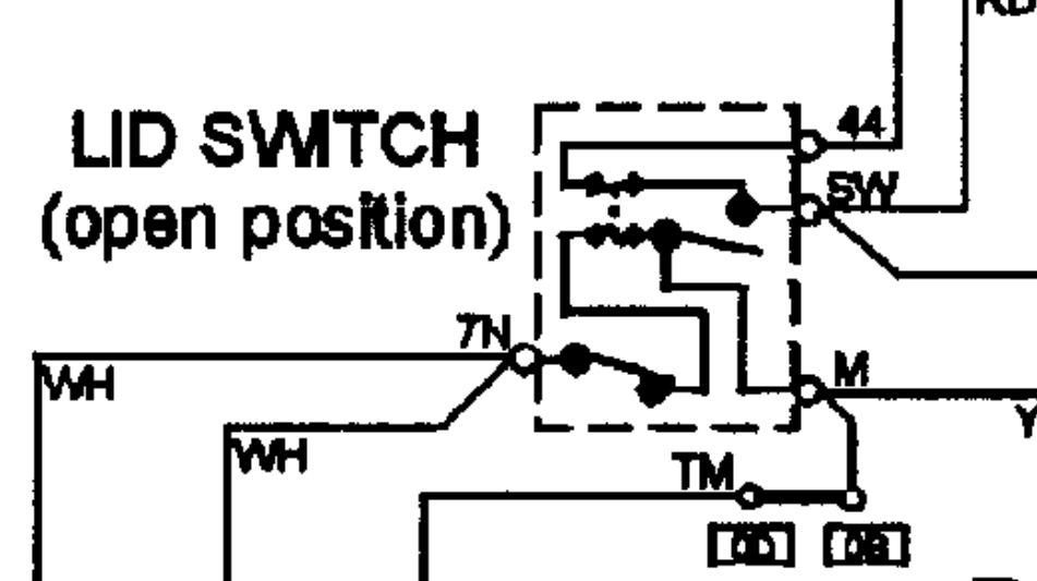
Now they just have a dot instead of a line between those two lines — and now the circuit makes much more sense! No shorts here. As for what they’re trying to show with that dot, I’m not sure. They certainly don’t give us any help in that department on the tech sheet (no label or anything). My guess is that it’s perhaps an odd way of representing a fuse.
It really doesn’t matter what the exact number of your meter’s input impedance is on its non-LoZ settings. 7.8 megaohms is going to be just fine — that’s effectively open as far as the circuit is concerned.
The important part is just that you don’t use LoZ when measuring sensor voltage, since that’s voltage that’s not supposed to be running a load.
This question is specifically asking about the board’s power supply, so J1-4 is the correct answer for that.
As for the connection to J2-6, I believe that you’re correct — that would seem to be a sensing line so that the board can tell what state the switch is in. Good spot!
The refrigerant does have a very low boiling point — that’s a key factor in how the refrigeration system works. But the other central concept is that, when something changes state from liquid to vapor, it absorbs heat energy from its environment to do that. So when liquid refrigerant flashes from liquid to vapor in the evaporator, it’s sucking in heat energy from the compartment in order to make that phase change.
We continue to cover this concept later in the course, so don’t worry if it doesn’t 100% make sense right now. But keep it in mind as you continue.
It all has to do with how pressure affects the boiling point. Remember that the higher the pressure, the higher the boiling point. So in a high pressure environment, like the high side of a refrigeration system, the refrigerant can be very hot and still remain a liquid.
Since you brought up water, you can also think of it this way: if you put some liquid water under a bunch of pressure, you could heat it well beyond its normal boiling point of 212 degrees F and still have it remain a liquid. Conversely, water that’s at less pressure than standard atmospheric pressure will boil at lower temperatures than 212 F.
I would also recommend that you review unit 3, since it talks all about how pressure affects a material’s boiling point. If you’re still confused, let me know.
Yep, you’ve got it — the three circuits with single elements are conflated into one circuit in this schematic. A little tricky to spot, but once you’ve got it, it’s pretty straightforward.
Yes, the inverter both turns its 120 VAC power supply into DC, and then commutates it through the switches. It’s the whole package!
You’re correct that the inverter is the component that provides the motor with its power supply. But remember that all motors effectively run on AC — that includes BLDC motors, like the compressor in that diagram.
The inverter’s job is to take standard 120 VAC 60 Hz line voltage and turn it into relatively high DC voltage, which is then electronically commutated into three-phase AC power via the inverter’s semiconductor switches. If you need to review that part of how inverters work, the first video in this unit covers it pretty well, so I’d recommend giving it another watch.
April 20, 2021 at 6:49 pm in reply to: Module 2, Unit 6, inverter compresor systems quiz question #5 #21757You’re right that 12.2 is technically slightly outside of the 3% tolerance — but only barely. It’s still close enough, and so your answer is correct: the compressor windings are good.
The only thing that can cause a compressor to build pressure inefficiently is mechanical failure — typically leaky seals. That manifests as either the reed valve that lets refrigerant into the compression chamber leaking or the seal around the piston itself leaking.
The only thing a run capacitor would affect is electrical efficiency. It would not affect the compressor’s ability to build pressure. The compressor would do its job just fine, but it might use a few more tenths of an amp to do so. Really not that big of a deal.
We don’t come across inefficient compressors that often. When you do come across one, the kind of symptoms you’ll see will all be effects of the compressor not doing its job of building up pressure. You’ll have cooler condenser temperatures relative to room temp, lower high side pressure, higher low side pressure, and poor cooling.
There’s no reason not to use LoZ for that test. In this particular case, the normal VAC function worked just as well. But he probably should have used the LoZ function, just to make extra sure that the measurement results were accurate. Good spot!
When it comes to AC voltage measurements, I can’t think of a situation where you shouldn’t use a loading meter when troubleshooting. It’s just a strictly more reliable test.
Now, if you’re measuring DC, that’s a different story. Oftentimes you’ll find yourself measuring low voltage DC data signals, and you shouldn’t use a loading meter on those. But again, that’s DC. As far as AC is concerned, a loading meter/LoZ setting is always the way to go.
Let’s take a step back and talk about how voltage measurements work for a moment. Whenever you do a voltage measurement, what you’re doing is measuring the voltage difference between two points. That’s why you need two probes to make a measurement. You’re always comparing one point in the circuit to another.
A standard (non-loading) VAC measurement compares those two points without putting a load on the circuit. In other words, the meter’s resistance is so high that no current flows through it while it’s doing a measurement. What this means is that you can get fooled by ghost voltage, which is what the video that Scott posted was showing. The meter showed about 108 volts, but it was just measuring a floating wire with no valid power supply.
The point of a loading meter is that while it’s measuring the voltage difference, it’s also acting as a load in the circuit itself. That’s always desirable when you’re measuring AC power supplies, since you want to make sure that the voltage you’re measuring is actually capable of driving current.
So yes, for your example of measuring the AC voltage voltage supply to a van, you would certainly want to use a loading meter, since you want to make sure that you have both a good line and a good neutral going to the load. A loading meter tells you that with 100% certainty.
Does that clear things up?
-
AuthorPosts