Forum Replies Created
-
AuthorPosts
-
Would that triac still be closed, therefore reading 120VAC between the pin connectors on the board itself where the molex plug was connected,
Triacs need two things to conduct electrical current: a valid gate voltage and current moving through the working anodes. So if the molex is unplugged, the triac will not conduct because electrons cannot move from anode to anode. This is why the engineers say that triacs are current-controlled devices. There’s a blog post at Appliantology that explains all this is excruciating detail. Check it out: https://appliantology.org/blogs/entry/953-triac-operation-for-appliance-techs/
even though it’s not sensing any voltage drop since we disconnected the load?
Triacs don’t sense voltage drop but they do sense (and are controlled by) electron movement. If the molex is disconnected, you have created an open circuit and electrons cannot move. Hence the PN junctions in the triac will not collapse and so cannot conduct electricity (ie., allow electrons to move through the PN junctions).
couldn’t we just locate the yellow and black wire on the timer motor itself and verify voltage drop there? You stated it’s a pain to do that and i’m not sure how it would be
Absolutely you could. I said it *may* be a pain to work with depending on the particulars of situation. You’ll have to assess on the job, looking at things like access, probes fitting the holes, etc. The video was applying the concept of EEPs that you learned in Core to locate other electrically equivalent test points. Options, man, options! What you want on a service call is the quickest way to skin the cat and get the measurement you need to diagnose.
Glad to help! Let me know if you have any other questions.
There wouldn’t be neutral feeding the water valves, they would have L1 feeding them creating a shunt. So with the drain pump triac closed, our voltage drop between the water valves would be 0 VAC since there’s no difference in voltage.
Correct! And that answers your original question.
As to your followup question:
But on the diagram above it’s showing the drain pump triac open; so wouldn’t the meter read 120VAC between the two points you have labeled above, not 0?
That pertains to the hand-drawn voltage meter that I drew in to illustrate something I was talking about. So there’s some spoken context around that. But WITHOUT that spoken context and going strictly by what’s drawn in the schematic clip above, the water valves would be getting a valid 120 VAC power supply. But if there was something said in that explanation that’s confusing, please let me know the time stamp where I can review.
Voltage difference would be 120VAC
Let’s make sure we’re looking at the same schematic. Here’s a markup of the schematic showing the circuits for the drain pump and water valves:
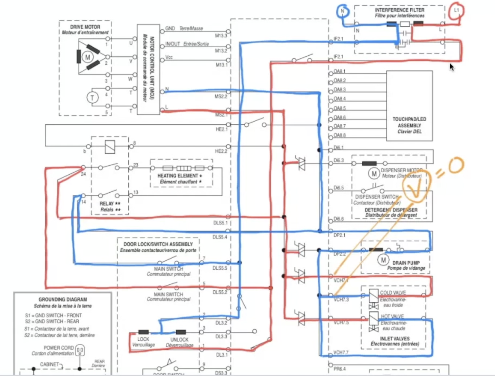
The circuits are drawn with the drain pump triac OPEN and the water valve triacs each CLOSED. Now, in your mind, imagine that the drain pump triac CLOSES. What happens to the Neutral supply to the water valves?
wouldn’t there still be voltage feeding the inlet valve, just no current being pulled since it’s not doing any work because it’s bad?
Hi Bryan. You are correct that L1 would be fed to the inlet valves if the drain pump triac closes. But look again at the circuit as annotated on the schematic. Look specifically at the voltage difference across the valves if the drain pump triac were to close.
POP QUIZ: If the drain pump triac closes and L1 is fed to the valves, what is the voltage difference across the valves?
HINT: Remember that electrons do not move on their own. Loads do not physically “draw” electrons. We use the expression “current draw” but this just a slang expression and is NOT a description of the physics of electrical current in circuits. Electrons (current) move in response to a voltage difference in a complete (closed) circuit.
Hi Denis,
Amazon or any decent local hardware store near you carry various crimp and twist connectors. They’re not very expensive. For example, here’s an Amazon link to a bell crimp connector set with 300 connectors that can accommodate wire gauges from 22 gauge (fine wire) to 10 gauge (beefy wire): https://amzn.to/3FmPLnl
Here’s a set of 36 ceramic wire nuts that accommodate wire sizes from 18 to 8 gauge: https://amzn.to/4dLLTcf
Let me know if you have any other questions!
Scott
Even on VAC, the reading between Neutral and Ground should have been 0 VAC. Double check that reading with your new meter and make sure of your test point locations.
Unlikely you damaged the board because its internal thermal overload probably did its job and opened the power supply to the motor windings.
Cord was installed properly but found 120 from neutral to ground.
If this reading is correct, something is miswired. Should be 0 VAC between Ground and Neutral. Ground could be floating (not connected). Did you make this measurement with a loading meter (LoZ) or on VAC?
If L2 and Neutral were reversed, then the motor was running on L1 to L2– 240VAC. That would explain the winding noise. If you let it run for a while like that, you may have damaged the motor.
If the load opens, no electron flow.
Correct
It would lose neutral and no longer have current.
Careful– If the load itself opens (breaks, whatever) it will still have Line and Neutral but because of the physical open inside the load itself, electrons will not move in the circuit.
I was confused why we were not considering the thermostat as a potential issue
No reason, just wasn’t the problem scenario we picked for this case study.
But here’s the key: If the thermostat was stuck open, say, (bake contacts stuck open) you would still troubleshoot the same way– starting at the Load of Interest (inop ignitor) and working your way back in the circuit until you found the missing voltage.
Just remember that troubleshooting always starts at loads, not switches. That’s why step 3 of the Tango is selecting your Load of Interest. Ideally, it starts in step 1 with the LOI being named in your problem statement.
Luckily, this schematic says it.
Another trick with tech sheets is to read everything on them. There’s usually not much but what is there may be just the thing we need to know to figure something out.
This one sort of confused me, I’m not sure why.
That’s normal and also why this tech sheet was chosen for this case study– to get you used to working from different tech sheet layouts and schematic “styles.”
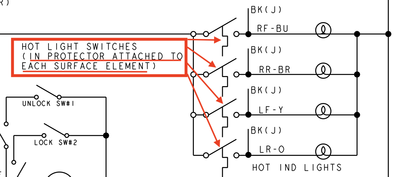
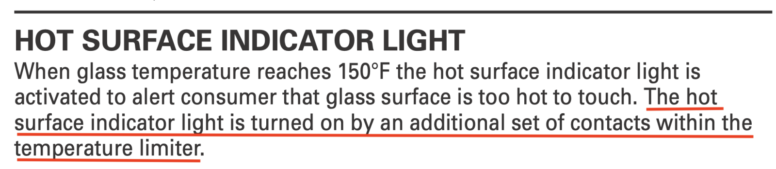
One thing that confuses many techs is following the black jumper wires for the indicator lights and, more importantly, to understand the circuit algorithm. The jumper effectively creates a logical OR condition for when the hot surface light comes on. It will turn on when EITHER the element is turned on at the infinite switch OR if the temperature is still above 150F.
Keep asking questions if you’re confused. We’re happy to help “unconfuse” you. That’s why we’re here!
I read in a different response that the entire surface element will need replaced because the thermal limiter (is this another term for the bimetal portion?) is part of the element. I’m not sure I would have known that,
You should– it was covered in the video in Module 2 Unit 7.
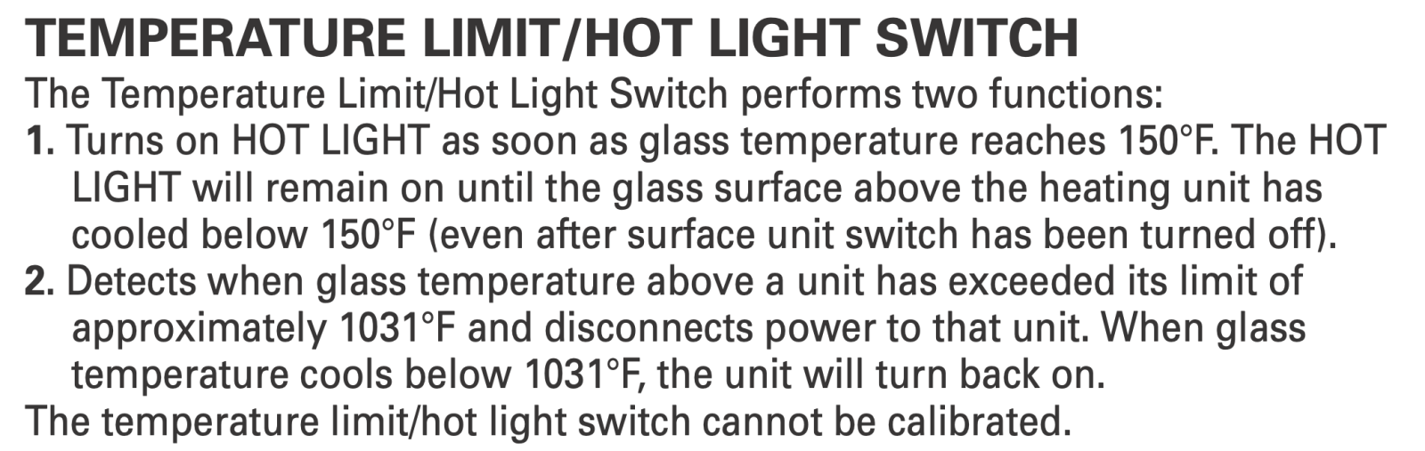
The thermal limiter controls power to the ribbon element. But there’s a separate bimetal attached to the element can with it’s own bimetal contacts just for the hot surface indicator light. This, along with the thermal limiter is part of the surface element. The way I know that is because the tech sheet for this case study explicitly says it (plus it’s standard technology used in electric cooktops):
Also from the same tech sheet:
but I do remember the box for the thermal limiter that is not present on the type that uses an RTD
RTDs are used in ovens for temperature sensing. So I’m not sure what you’re asking. Try again?
If the issue was that the supply voltage is dropping below 120 (to 110) and therefore the current is dropping below the minimum required to have the gas valve open – how do we detect or fix this? I
As with all AC loads– like the ignitor and valve heater– you begin with an amp measurement just to see where you’re at. If amps are low, then verify your voltage supply. You are correct that if volts are low, amps will be low, I=E/R. I and E are directly related. So if E goes down, so does I.
The Molex G-1 and G-2 – what is this? Can I always assume that a wire passes directly to the other side and continues its path?
Molex connectors are used all over the place in all appliances. It’s a plastic wire harness connector that connects to a mating connector on a board or somewhere else. It’s like a removable splice so the wires pass from one side of the connector to the other to continue the circuits that it’s connecting. So you read the wiring diagrams with the understanding that the connecting ports (or pins) of the molex pass straight through to the other side.
If the issue is the thermostat, would the ignitor not glow at all?
Define “issue”.
A circuit-based question would be, “if the thermostat is OPEN, would the ignitor glow at all?”
What does a load need to do its work? A power supply connected to a complete circuit.
The power supply for the load (the ignitor and bimetal heater in series with each other in this case) is L1 and Neutral. The load gets its Neutral through the bimetal heater and L1 through the thermostat. From N to bimetal heater to ignitor to L1 is one series circuit with two loads in series.
Pop Quiz: What happens to electron movement in this series circuit if either load opens?
Bonus question: What would happen to electron movement through the ignitor if molex pin G1-2 pulled away and separated from pin G2-2? (this sometimes actually happens in real life)
But in this case they jump the gap (understand that aspect), ignite the gas, hit the burner head, and go…. where?
The electrons are jumping the gap from the electrode TO THE CHASSIS (via the burner head and base). The spark module can detect this electron movement. It sounds amazing, but that’s what happens.
If you’re asking HOW the module detects this current in the chassis, that’s the FM. And really, we don’t care because the spark module is treated like a “black box” that does strange, mysterious stuff that we don’t need to know. We just need to know how to troubleshoot it. And to do that, you need to know what are it’s required inputs and what are the specified outputs. If we know that, which is what you learned in the course, then you know all you need to know in order to troubleshoot accurately and correctly.
When it comes to circuit boards and special modules, like spark modules, we troubleshoot them by looking at inputs and outputs. We don’t really care how it processes those inputs, only that it produces the correct outputs. That is called “black box troubleshooting.”
-
AuthorPosts