Forum Replies Created
-
AuthorPosts
-
The current that is detected via “FM,” where do these electrons go?
They go to chassis, the same electrical location of the reignition module ground screw. The burner head and the ground lug on the reignition module are EEPs. The FM module in the reignitor detects these amps. We’re talking MICRO amps, like 0.000001 amps. That’s the FM.
This spark doesn’t result in any shock risk?
Yes, in the same way that a static electricity imparts a shock. You’ll feel it but probably won’t die because the current is not sustained– it is interrupted and pulsing. Electricity kills by continuously pushing electrons through your body, burning up tissues and organs as it goes.
Current/spark jumps to the burner head. Does the current actually return to the spark module’s ground (the spot on the bottom when screwed in) for the flame sensing?
Correct– the spark jumps the 3 mm gap from electrode to burner head. The burner head is supposed to be in direct contact with the burner base and therefore chassis. The 14,000 volt spark is caused by electrons screaming through the air and oxidizing oxygen molecules which produces the visible spark.
Remember that “current” is just a name we give to a directed stream of electrons. Well, that spark IS is a directed stream of electrons. The ground lug on the spark module detects this current using what we call “FM technology” (FM – F*cking Magic).
I said previously that the burner head is supposed to be in good metal-on-metal contact with the burner base. In the real world, sometimes pots of possum stew boil over and leave food gookus underneath the burner head. This gookus acts as an insulator that blocks the spark electrons from entering chassis where it can be detected by the spark module. So a good quick check on a re-ignition problem where it keeps sparking after flame is established is to check the burner head and base for cleanliness and ensure good metal on metal contact.
2. In unit 9, you write that the neutral is “unswitched.” What does this mean?
Meaning that if you look at the Neutral line on the schematic from source to load of interest, there shall be no switches in that line. Just hardwired Neutral from source to load.
But can you elaborate on what pull off looks like? Does this just mean pull out one of the pins? Does the whole connector come off?
It will vary by the appliance and how the manufacturer wired the loads. Sometimes it’s a molex harness connector. Sometimes it’s individual wires connected by single terminals. There are multiple ways to skin the cat. As long as you know what you’re trying to do electrically, then the mechanics of disconnecting is obvious and straightforward.
You got it!
This business with the computer board making software decisions about supplying voltage to a load or not is common today with computer-controlled appliances.
Keep in mind that computer-controlled appliances really ARE computers. Instead of powering loads like a monitor, keyboard or printer like our desktop computers, they power loads like heating elements, compressors, fans, LED displays, solenoid valves, etc. So this concept of software-controlled power supplies is an important one to keep in mind when troubleshooting modern appliances.
Even if the manufacturer does not explicitly tell you about software-controlled power supplies, it’s usually there in some form and implemented through things like POST and sensing lines. Just keep this in mind so you don’t get head faked by this.
Classic example is Samsung refrigerators. If one of the evaporator fans get stuck (say by ice) and the board is not getting a speed signal back from the fan motor, it will kill power to the affected fan motor for 15 minutes and try again. It will repeat this three times and then throw an error code. The only way I know this is because Samsung explicitly tells us this in the Fast Track.
… but the Amana only had resistance specs. In this situation would you just work with the resistance specs if that is the only spec you have…
Exactly. We work with the specs we’re given, not the specs we wish we had.
An exception to this is implicit specs.
Example: You’re given a wattage spec on a heating element. As an MST student who has learned Ohm’s Law, you know that amps are an excellent surrogate for watts. So you fire up the element and measure amps. If you know volts and amps, you can calculate watts using everyone’s favorite formula: P=I*E. You plug in the volts (E) and amps (I) that you measured and get watts. Then compare this calculated wattage to the specified wattage to see if you’re in spec.
Not so easy in the case of thermistors because they are in what’s called a “voltage divider circuit.”
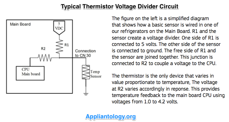
So it’s not a nice, straightforward Ohm’s Law calculation.
Pop quiz 1 = 240 (subtracting a negative is the same as addition)
Correct!
Pop quiz 2 – You would not measure a difference. The 120 volts coming from L2 would be present at both points, so the difference would be zero.
Correct again!
Bonus – I think it was called half splitting, but I remember the technique from the core. I think it would be good for me to review though.
Correct yet again!
Sorry to keep you, feel free to move on.
It’s fine, that’s why these forums are here!
In this case, the element is bad. So I can’t measure L2 on both sides of the element. This is what I mean, whether or not it is correct….
This is correct. If the element is open, it’s electrically the same as the two wires being disconnected from the element and measuring at the disconnected wires.
The element is open, whether it is the element or the connections etc., current can’t pass through it.
That’s right.
Scenario 1: the board has killed power to P1-1 because it does not sense the bake element, but it has not killed power to P2-6 because L2 is present for the upper right convection element (we assume). As long as P1-1 and the connecting wires are still intact, would I still measure 120V, because this is the difference between the V being supplied by L2 wrt L1 (the open bake element is not allowing current from L2 to reach the other side)?
No. If P1-1 is electrically open (because the board is not closing the relay to supply L1, for example), then you’re measuring the voltage difference between L2 and Open. This is a situation where, if you’re not using LoZ or a loading meter, you may measure some ghost voltage but you are not measuring the difference between L1 and L2.
Here’s a video demonstrating ghost voltage in a wall oven that looks eerily similar to the Acme wall oven in this case study.
Scenario 2: the board hasn’t killed power, and I would read 240V regardless of the open status of the element because the difference between these two points, due to being out of phase, is 240V.
Correct!
Or I guess I might see 120volts? Because L2 would still be active (bc the convection element is working)
Remember that when we talk about “voltage” in a circuit, it’s shorthand for saying, “the voltage difference between two points.” That’s why it takes two leads to make a voltage measurement.
In a 240 VAC circuit, you have L1 and L2. L1 and L2 to Neutral is 120 VAC. L1 to L2 is 240 VAC. But if each Line is 120 VAC wrt Neutral, then how can you have 240 VAC from Line to Line if it’s supposed to be a difference between two points? Don’t they simply add the 120 VAC together to get the 240 VAC?
Nope. Still a difference, meaning L1 MINUS L2. (Or L2 MINUS L1, works both ways). It works because L1 and L2 are 180 degrees out of phase with each other so, wrt Neutral, they are two distinct phases of voltage. In a split phase power supply, like most residences in North America, the two phases are 180 degrees apart. Meaning that when L1 is +120 VAC, at that same exact moment in time, L2 is -120 VAC.
Pop Quiz: What’s +120 VAC – (-120 VAC)?
What all this is getting to is realizing that, in a 240 VAC load, like the bake element in this case study, if one Line is missing, you will still only read 0 VAC across the element even though the other Line is present.
And how can this be? Because he IS the Kwisatz Haderach!
Sorry, I had a Dune moment.
Pop Quiz: Suppose L1 is missing but L2 is present (vice versa is same outcome). You place your meter probes on each element terminal and energize the circuit. What voltage difference will you measure?
Bonus Question: What troubleshooting move might you deploy to determine which Line is missing?
Voltage looks like p1-1 to p2-6.
Correctillia!
1. I followed the case study and understood. But why aren’t we checking voltage before ohms? Is this because we figured it was the bad element based on the error code and logic? I know live tests are preferred, I figured we would want to check that the board was providing L1 and L2 appropriately before relying on an ohms test.
Excellent question! You said the answer: we’re getting an error code for the upper bake element. That means the board is sensing the presence of the element during its POST (power on self test). Since the schematic/wiring diagram does not show a sensing line (a switched line back to the board), it is probably doing this via current sensing. You need volts to make amps.
Also, since the board is throwing this code, the usual algortihm is to kill supply voltage to the coded component. So measuring voltage may not be an option.
But still, checking the supply voltage is a solid troubleshooting step.
Pop Quiz: Where would you place your meter probes to see if the upper oven bake element is getting its supply voltage?
2. The upper right convection oven element, we assume, is functioning properly because there is no error code. Does the bake element get L2 through this convection element? Most of the schematics are not drawn like this (this being a wiring diagram). I mean, based on the drawing, it is impossible for the upper bake oven to get L2 if the convection oven is not getting L2. Is this correct?
Look carefully at the schematic section with the upper bake element.
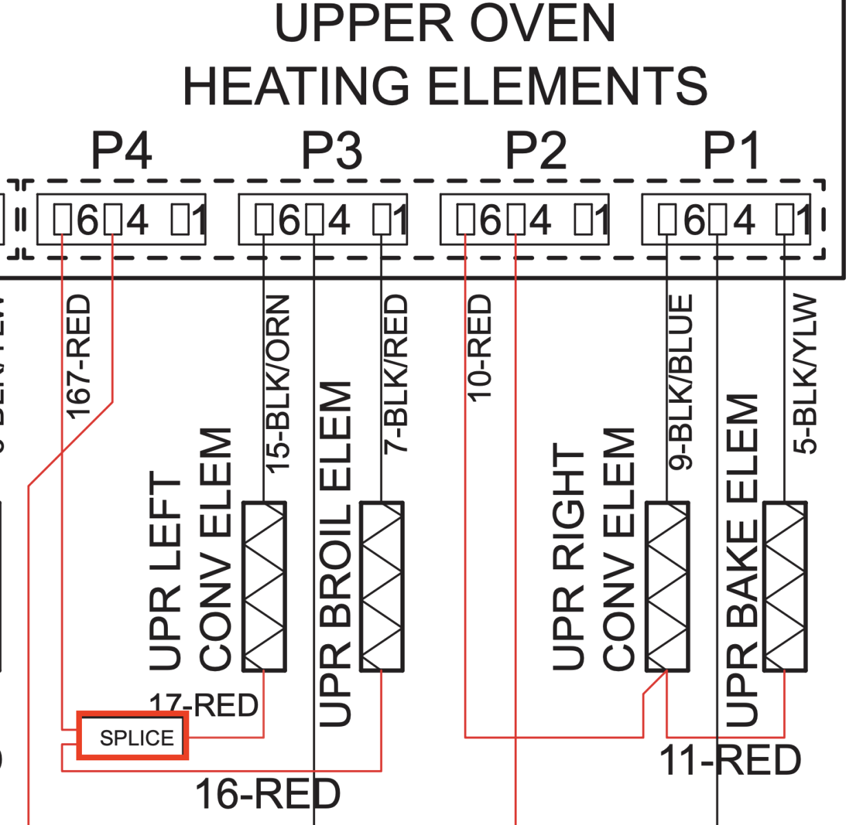
See how the line for the bake element tags off the connection to the convection element? That means L2 for the bake element “daisy chains” and goes on to the bake element. The bake element and the convection element are in parallel, not series. You will encounter loads in series in appliance repair but this is not one of those times.
Also, manufacturers play loose with the terms “schematic” and “wiring diagram”. This diagram is more like a pictoral schematic. The simple distinction between a schematic and a wiring diagram is this: if you can easily trace the power supply circuit for your LOI on a diagram, it’s a schematic, not matter what the manufacturer calls it.
3. Can I circuit breaker on without the heat on for the oven, and disconnect only one of the connectors to measure ohms? The question seemed to imply I need to either kill power or disconnect both sides. Can I just disconnect one of these and measure from the wire end to the other connector?
Yes. As long as the circuit for the LOI is dead AND at least of the leads to the LOI is physically disconnected (either at the load or at the EEPs for the load at the board), you’re good to go.
Good questions, keep ’em coming!
Almost half the service calls I go out on are appliances I have never disassembled. Especially true for the warranty calls because they’re so new. This is where prediagnosis makes all the difference. I always get the model number for every service call. I pull all the technical literature for that model and load them on my ipad. I’ll review the schematic with the problem statement to select my load of interest and read its circuit. I’ll bookmark any relevant disassembly instructions for both troubleshooting and repairing so everything is ready to go on my ipad.
Here are three workshop videos you should watch. You’ll get a lot more confidence for runnning calls after you’ve watched them.
The Samurai System for Service Call Excellence
Appliance Service Call Structure and Troubleshooting Strategies
Troubleshooting Strategies for Computer-Controlled Appliances
1. Knowledge check – hypothetical. Is there any reason I can’t do a similar measurement to the answer by disconnecting PR1 and measuring the PR1 wire end to the DLB connector? If yes, thank you. If no, can you explain.
That would work!
2. For the stretch question of calculating ohms, how do I know if I should use the 3600 of 4000 watts? I see it is based on the size but did I miss this somewhere?
When they give a range like that, I just use an average value. So in this case, if you use 3800 watts and work the problem, you get a little over 15 ohms. There’s only one answer close to this.
3. Generally, to this point, I have understood the concepts and answered the questions correctly. But I consistently am asking myself how to physically do the tasks. For example, how do we access the oven relay board? How do I replace the TCO? Is this information that will be called out elsewhere in the manual for the appliance, covered later in the course, or just something that needs to be learned outside the course?
Do you have your Appliantology membership yet? You’ll get disassembly help from service manuals and Youtube videos. You can download service manuals from Appliantology. You can also get lots of disassembly insight from the exploded parts diagrams available at Appliantology or many online parts vendors such as AppliancePartsPros.com.
Disassembly is the easy part of our job. The hard part is troubleshooting. This is the lost skill in the appliance repair trade today. Many guys will start tearing down right away. This is NOT troubleshooting!
The rule is this: Minimal disassembly for troubleshooting. Save the teardown for the repair when you have the needed part.
Most appliances today are computer controlled. That means the main single-board computer often serves as a central troubleshooting location for the rest of the machine since “all roads lead to Rome.” That’s what EEPs are for. You identify these convenient testing locations from the schematic using EEPs.
RE: the GFCI question. The Heater Sensing works by sensing voltage between the heater sensing port and L1. GFCIs work by sensing a current imbalance between Line and Neutral. The assumption is that they should exactly equal and,if not, the missing current is going to ground, ie., ground fault.
So am I wrong for saying the heat sense circuit and isolating resistor are pretty much built in safety circuits for the type of conditions?
I’m not sure about safety because the other thermal controls are explicitly there for that purpose. I think the heater sensing is there to assist the technicians in troubleshooting. Especially since the tech sheet says that these codes are not displayed to the customer, only in service mode.
The isolating resistor is there to allow the heater sensing port to sense a grounded element. Heater sensing takes place before the heater triac or relay closes and with the motor running. If the isolating resistor was not there, the heat sense would not detect 120 VAC (grounded element). Understanding the distinction between voltage and voltage drop is critical to understanding this circuit algorithm. So study this concept well!
I’ve heard if the replacement drier that’s also the manufacturers appointed drier through the part number is slightly bigger,
So the OEM replacement drier is physically a little larger than the original drier that came with the refrigerator?
it won’t hurt the system to add an additional gram or ounce, t
Be careful here. There’s a big difference in volume between a gram and an ounce. There are about 28 grams per ounce. So while adding an additional gram to a systemn is not a big deal, adding an additional ounce is huge.
R600a systems are typically measured in grams. You have, what, about 55 grams of refrigerant, give or take? Other systems are measured in ounces. These system charges range from 5 to 7 oz. Let’s say it’s a 5 oz system. If you add an extra ounce, that’s a 20% overcharge!
In general, if the answer to my first question is “yes”, then I would not vary from the label charge unless the manufacturer gives specific guidancw for this.
Hi Jessica, are you referring to a mechanical thermostat or an oven that uses an RTD?
The old skool mechanical thermostats used a gas filled bourdon tube connected to the thermostat body. The gas in the tube expands and contracts in response to temperature. The expanding/contracting gas opens and closes contacts inside the thermostat body, thus controlling power to the heating element or gas ignitor.
If that’s not what you’re after, let me know.
The main take away from that section is the paragraph right above the gauge table. Note particularly the injunction against joining copper and aluminum wires.
Wire GAUGE is inversely related to wire DIAMETER. The higher the gauge, the smaller the diameter. Wire gauges are stamped on the insulation. It’s good to have a familiarly with these things since there are lots of wires inside an appliance!
Ampacity– the amount of amps a particular gauge wire can carry– is also inversely related to gauge. The higher the gauge, the less amps it can carry.
. Do you assume that all of those are connected to the control board? or to each other? In other words, do you have to have the appliance torn apart to fully understand which connetor connects to what?
“Molex” is the name of a company that has become used as a generic. Like Kleenex or Coke. So it’s a generic term used to refer to any type of multi wire connection, whether that connection is at a board or at a door hinge or wherever.
The relative location of molex connectors is usually shown on the schematic or wiring diagram. GE is especially good at denoting molex connections anywhere they occur right on the schematic without having to use messy wiring diagrams. They do this because someone at GE at one time understood that any molex connector is a weak point in a circuit because it is subject to corrosion, mechanical failure, etc. that wires are not vulnerable to.
-
AuthorPosts