Simple Circuit Survey
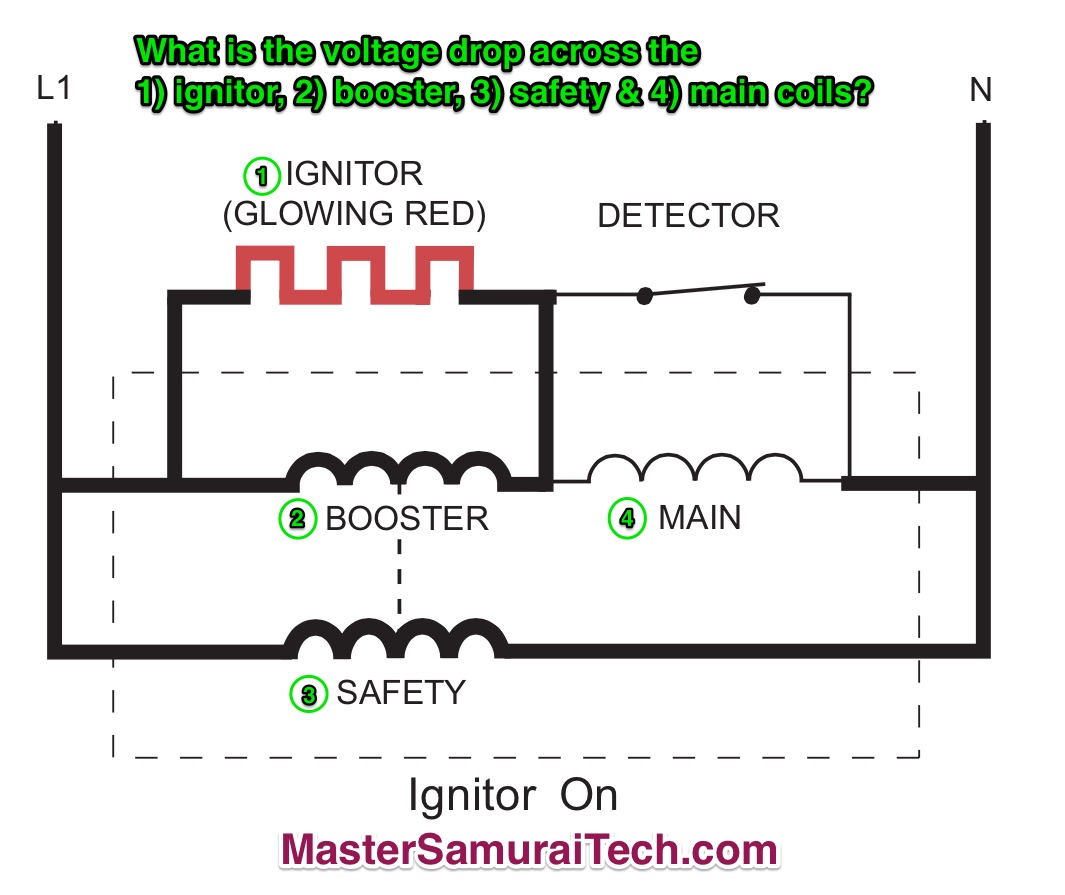
Start by noting the power supply. It’s called out as L1 to N. So we know that the power supply to this circuit is 120 VAC.
Ignore the thickness of the lines in the drawing; it doesn’t mean anything.
Since the ignitor is glowing, we know that 1) we have a valid power supply, and 2) current is flowing, so there will be a voltage drop across the ignitor (the load) and work is being done (producing heat).
Next, we note that the ignitor, booster, and safety are all in parallel with each other. From the Core Appliance Repair Training course, we know that the voltage in each parallel circuit is equal to the supply, in other words, 120 VAC in each leg. That’s just the way circuits work.
“But what about the voltage drop across the main coil— doesn’t that subtract from the voltage available to drop across the ignitor and booster?”
Ah, Grasshoppah, let’s look at that voltage drop across the main coil. Notice that the detector is closed. As such, it is shunting the current around the main coil because current will take the path with no resistance. Since there is no current flow through the main coil, the voltage drop across the main coil is effectively zero.
So the answers are:
1. Ignitor: 120 VAC
2. Booster: 120 VAC
3. Safety: 120 VAC
4. Main: 0 VAC
Still confused? Take the Core Appliance Repair Training course and hone those troubleshooting skills. Complete the free Sample Course and get a discount coupon!